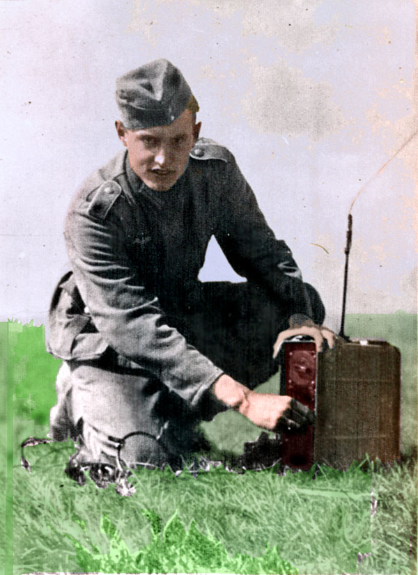
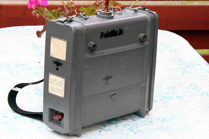
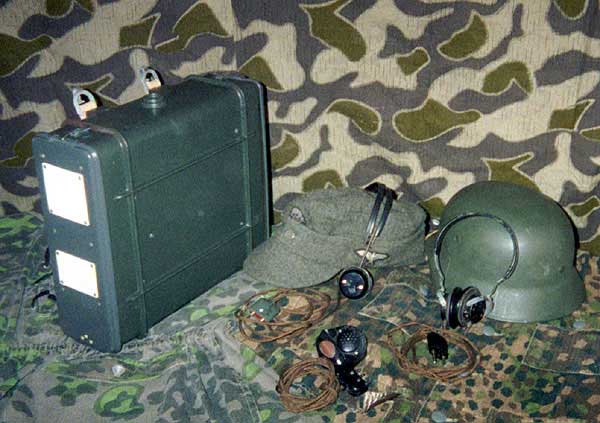
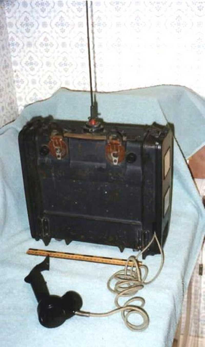
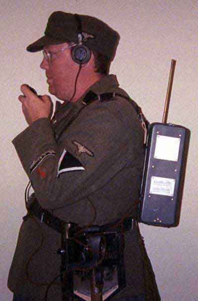
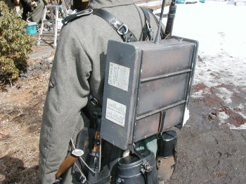
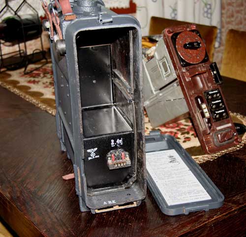
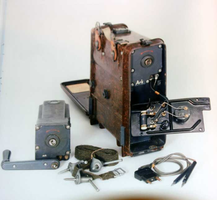
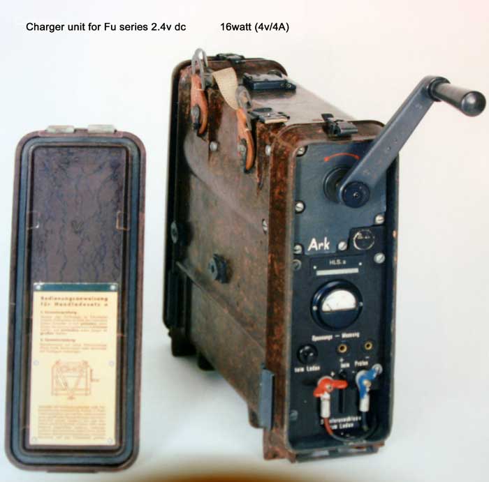
The Feldfu's were real backpack sets for mobile use and were powered by a 2,4
battery (Nickel Cadmium). During WW II the Germans produced huge quantities of
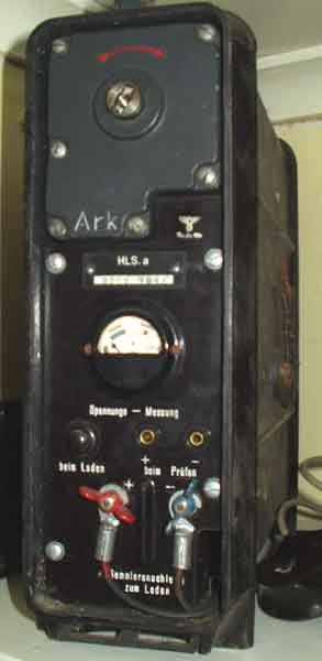
these batteries. An interesting feature was that the hand charger was housed
in a similar case to charge batteries when
operated, for instance, in remote trenches. Though, as usual for most of such
German equipment, they prepared it so as to be used during darkness as well.
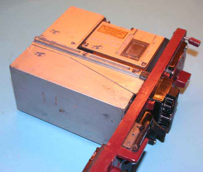
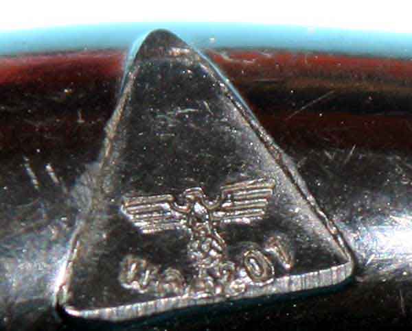
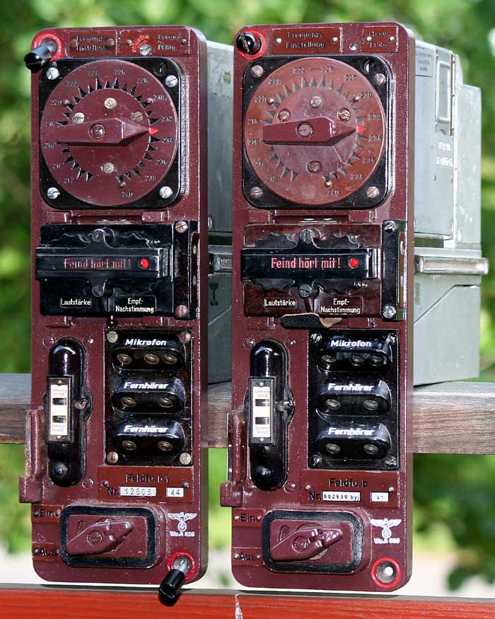
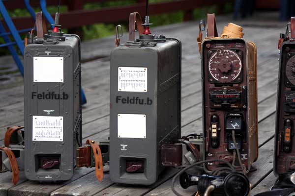
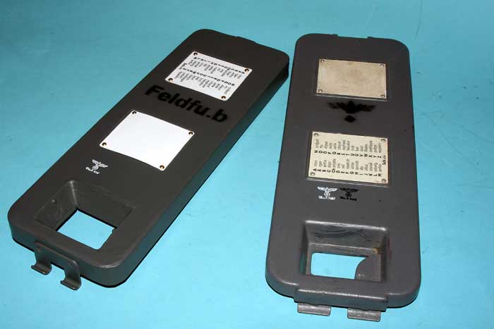
To recognise which set was for what frequency (b or c) but also its purpose
(like the HLa- Handladesatz) on the top of the set were placed dots and a kind
of metal hooks . Similar to Braille used by blind people. The Feld Fu b. was
of a later date, though because they also used a similar Feld Fu b, type they
certainly would have marked these sets too. The Feldfu's came into service
about 1940/41,as 2 tubes unit ( b-2) and later.better constructions,and
matrials.
![]()

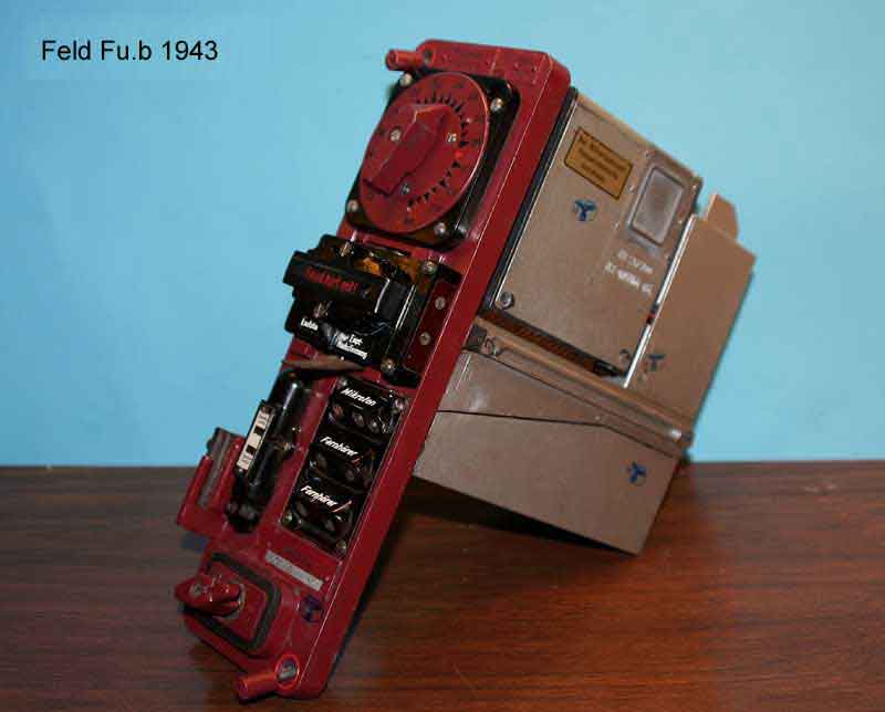
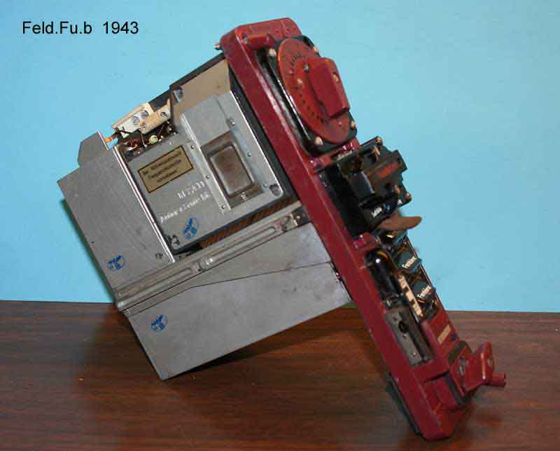
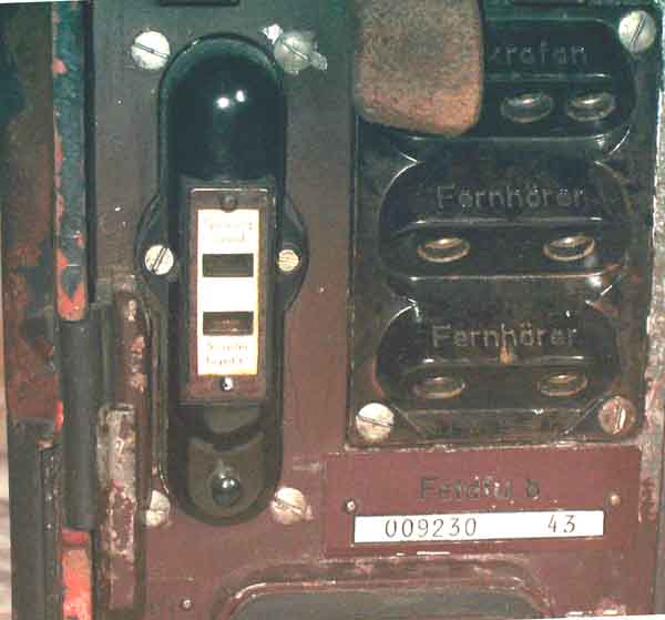
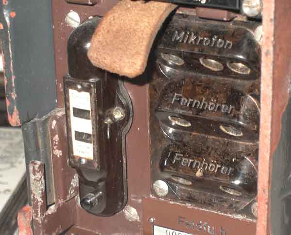
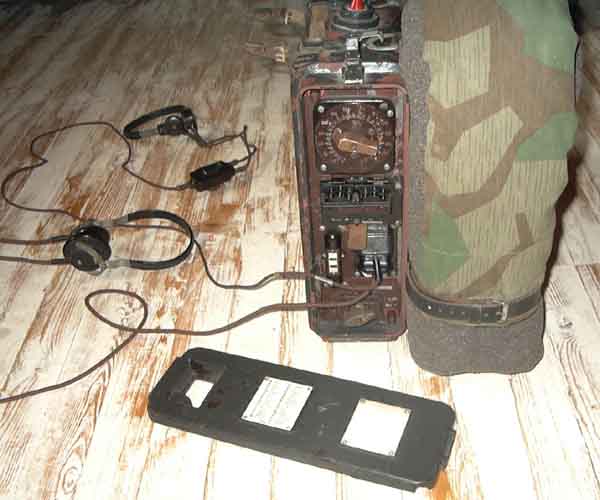
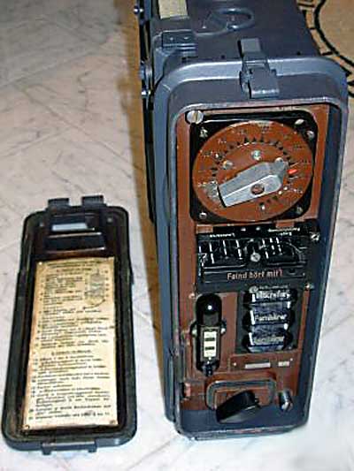
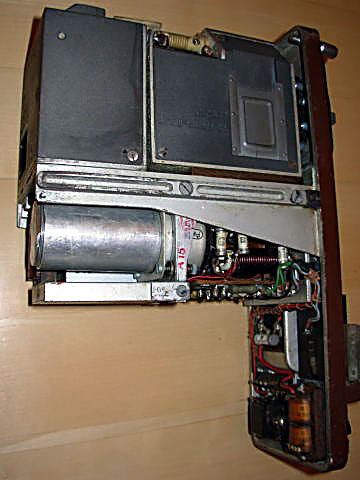
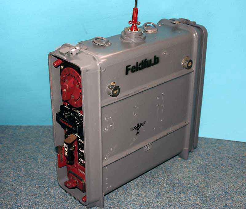
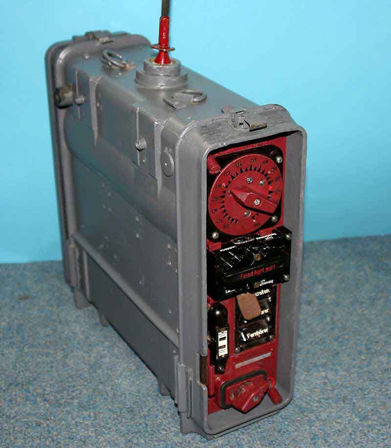
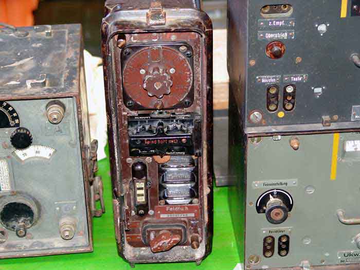
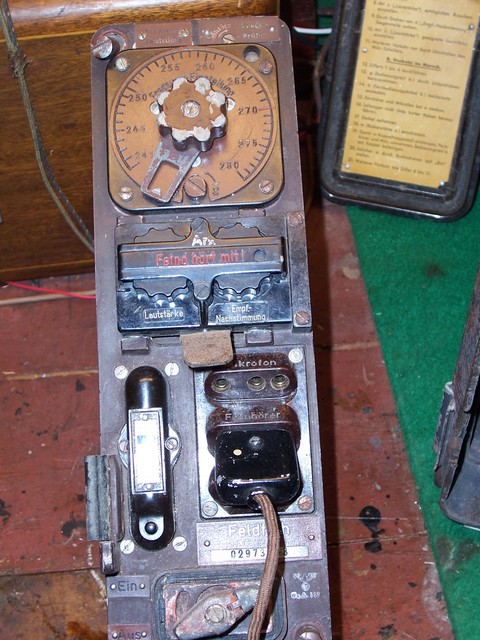
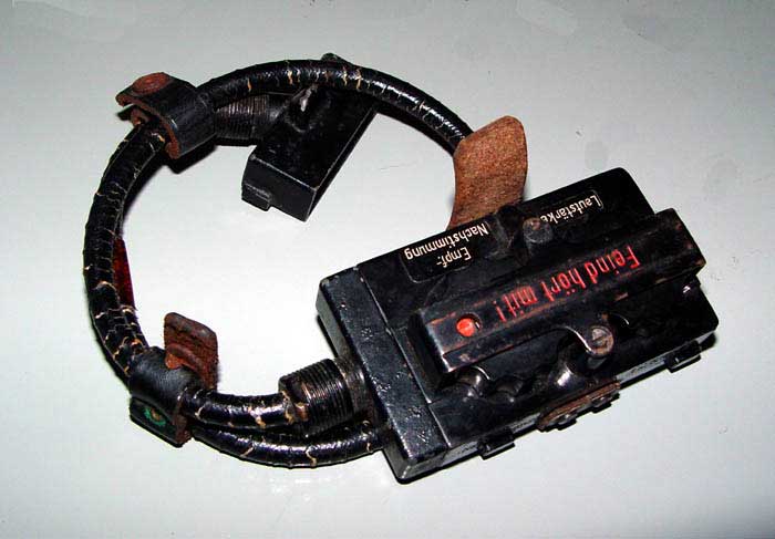
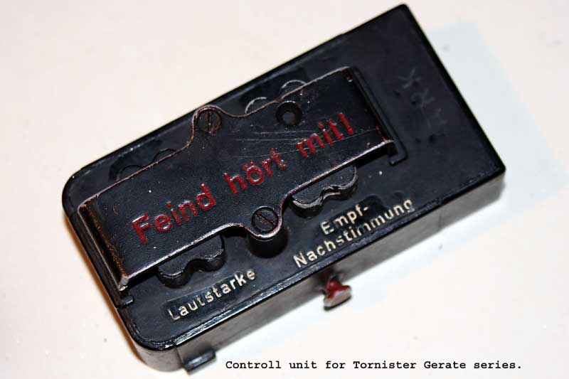
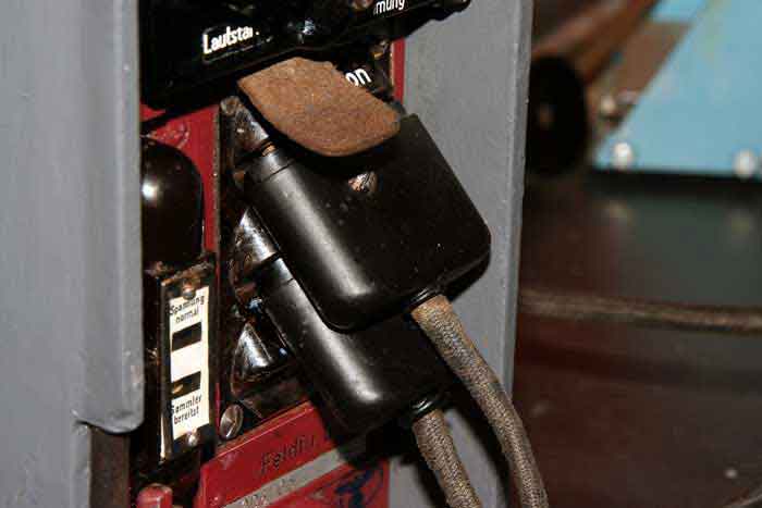
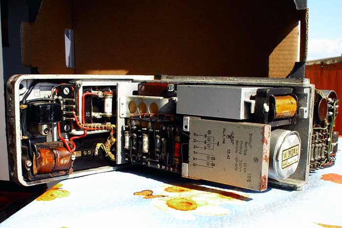
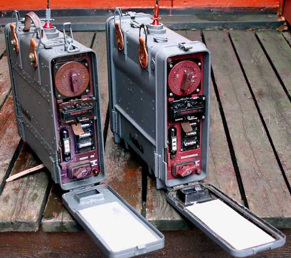
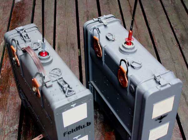
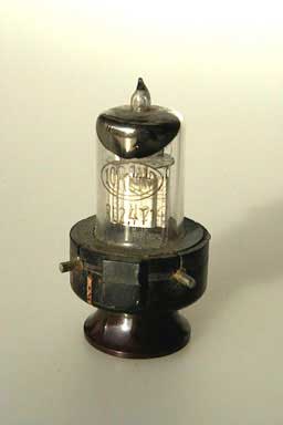
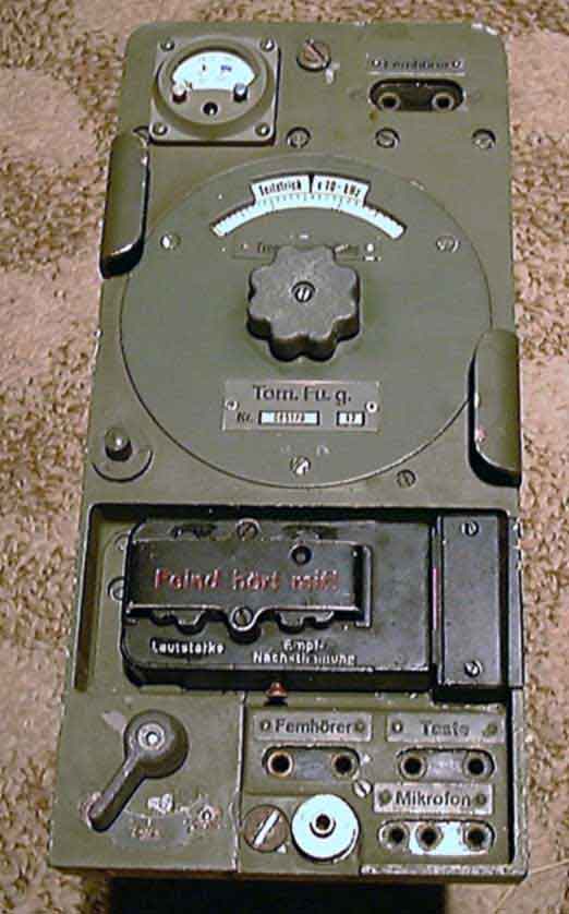
Tornister Feldfu.b /c/ f has 3 tubes, super-regenerative receiver. The frequence adjustment is a multichannel switch with a fine adjustment through a hole on the right upper side.The control head has a volume and freqadjustment.The adjustment of frequence is made of a master-piece of a electrical instrument coil,and axial- controlled butterfly condensator.The transmit distance is given around 1-2km but I have in light terrain ca 3 km.The radio has no squelch.The transmitter power is ca 120-150mw.Receiver sensitivity is ca 2uv-8db noise reduction.Model Feld.Fu.b-1 has 2 tubes, and no RF unit,but all over the same constructions.Feld.Fu.b and c models was produced by Lorenz (Berlin),Horny.A.G and Saba,most part of the factories stay in DDR after the war.The Russian army take over and begin productions of some military radio-equipment,as R-105D series.They copy the German Wehrmacht radios with some modefications to the better,almost change the regenerative receivers with superhetrodyne types.Later in 1947/50 some other "copies" from German radios seen the daylights.Well working radios and mecanical structure make this equipment to work after 50 years "of-air."
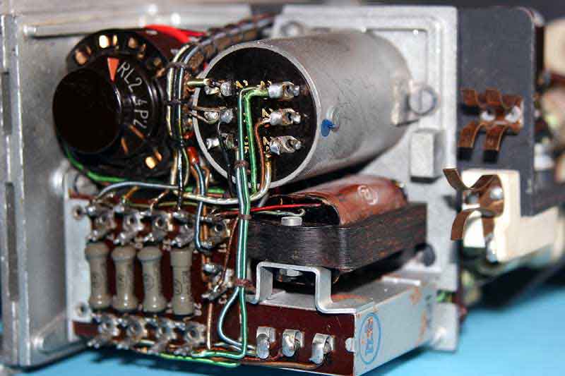
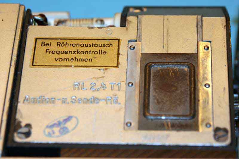
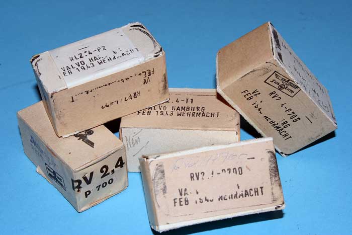
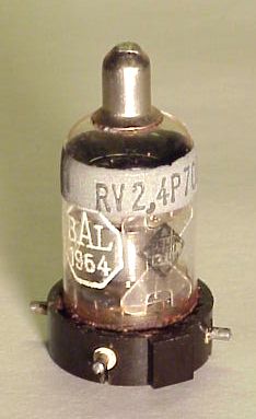
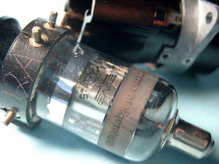
Tubes: 1-RV2.4P700 , 1-RL2.4P2 and RL2.4T1
![]()
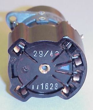

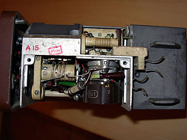
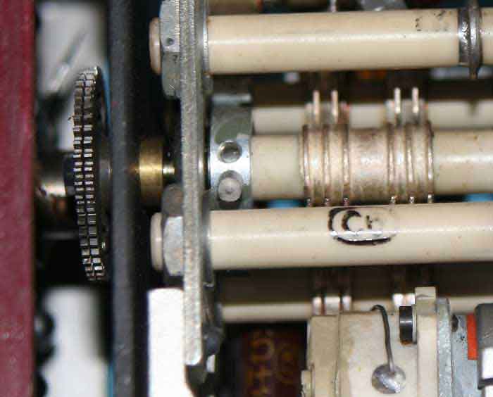
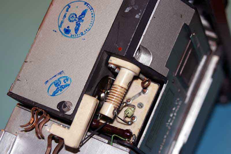
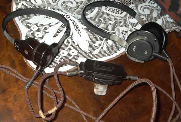
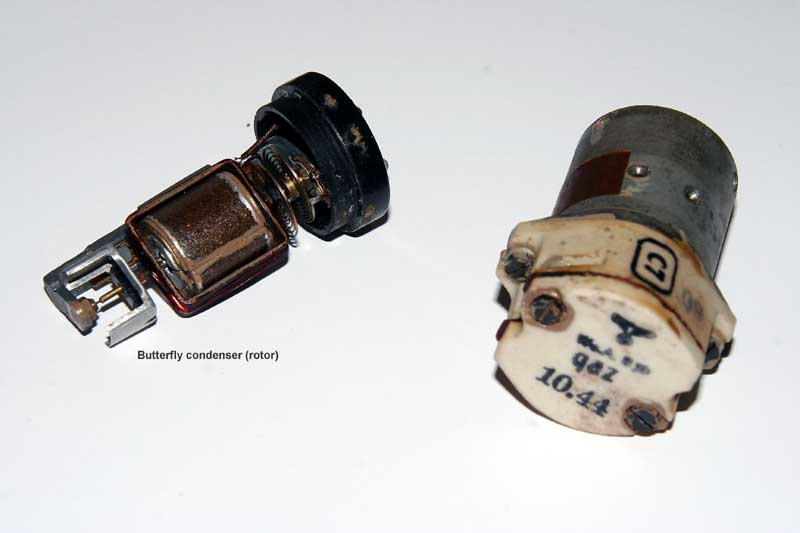
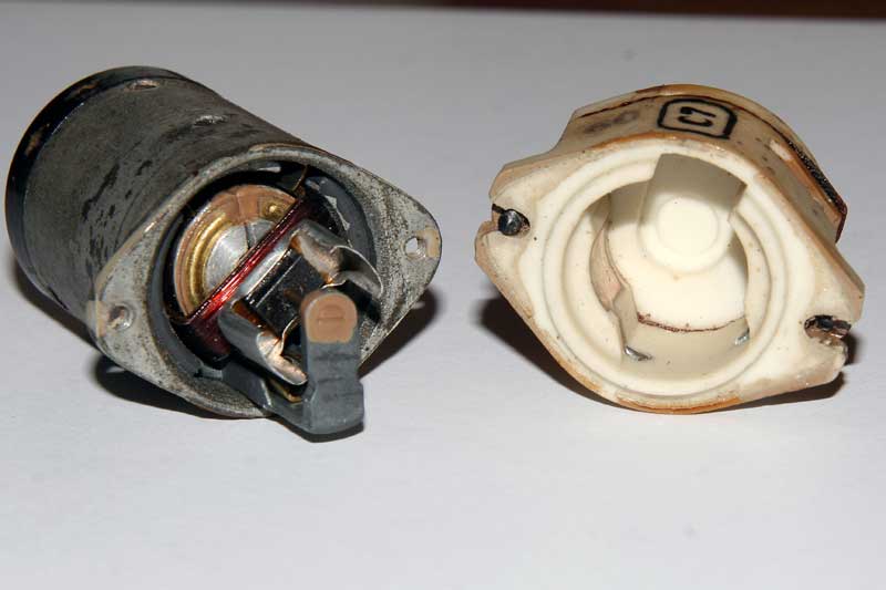
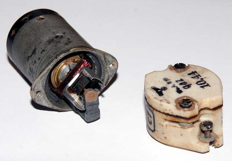
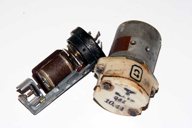
Closer picture of the "Moving coil" Types of my garnityr working with Feld.Fu series.
Here you see the ceramic moving coil controlling the butterfly adjusment condensator. A masterpiece. Hier sehen Sie die keramische bewegliche Spule, den Schmetterlings kondensator zu steuern. Ein Meisterwerk.
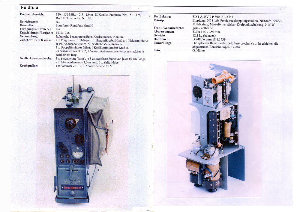 Feldfu a
Antennas.
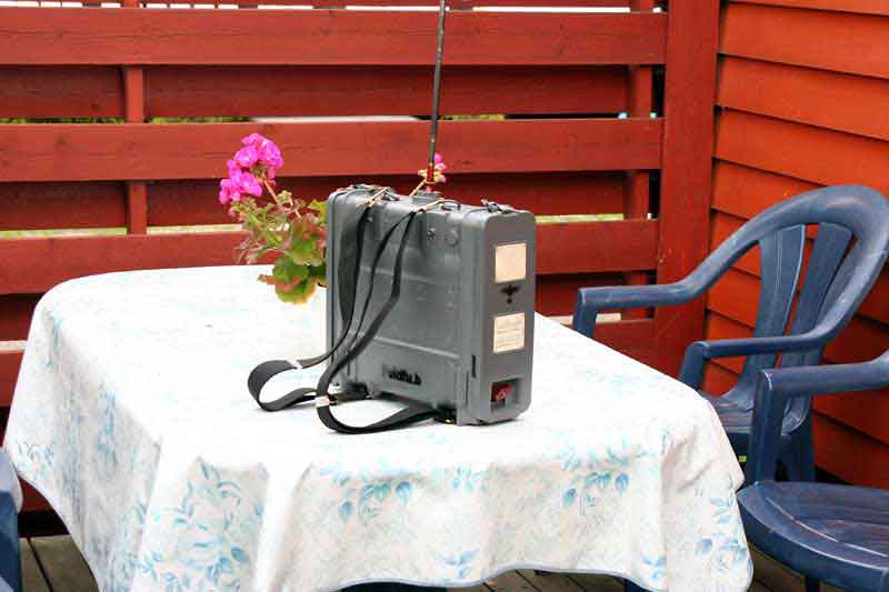
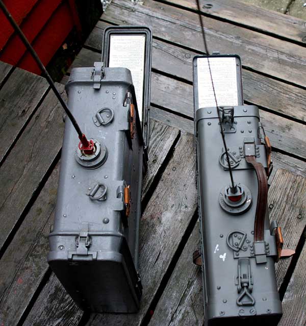
Feld.Fu.b are delivered with 2 types of antennas.The first model (1938-1941) have a antenna 110cm long whip in 2 pieces.Later from 1943 it is changed with a" band-antenna" 72.5cm long.
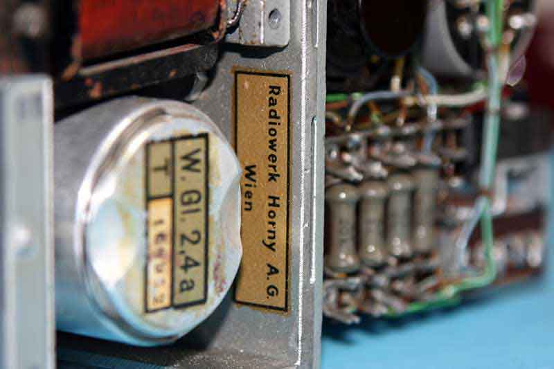
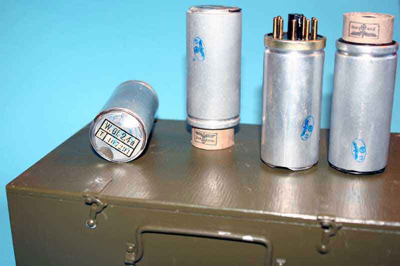
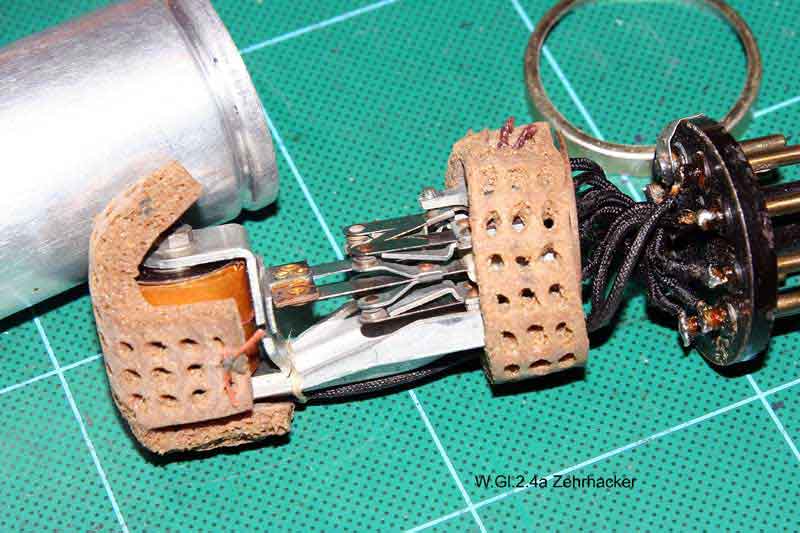
 There is a another type of vibrator power supply that eliminates the rectifier
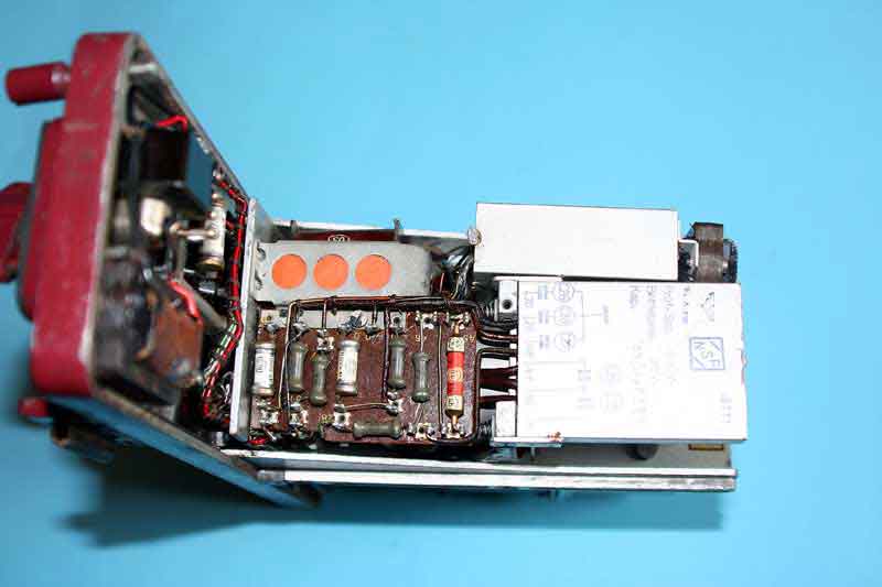
tube, which uses a synchronous vibrator. Below is a diagram of a
synchronous vibrator power supply. (Zerhacker
W.gl.2,4a)
There is a another type of vibrator power supply that eliminates the rectifier
tube, which uses a synchronous vibrator. Below is a diagram of a
synchronous vibrator power supply. (Zerhacker
W.gl.2,4a)
 The last one is the most used in Wehrmacht equipments from 1942 -1945
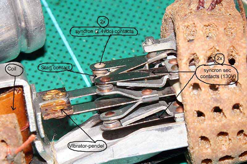
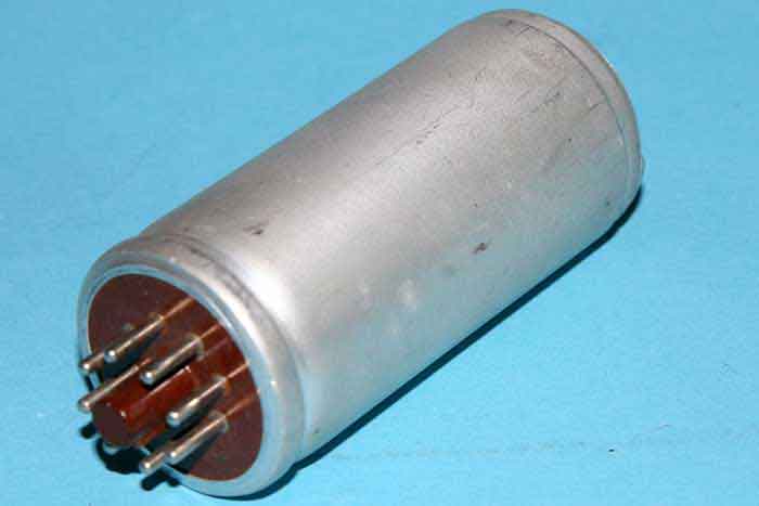
98% of the German vibrators W.GL2.4a would not work after 60 years in the orginal pack.The syncron contacts is almost free of dust,but the start contact need adjustment.The setting screw must be turned one degree with the clock.Opning the vibrator is some "tricky",so be care.
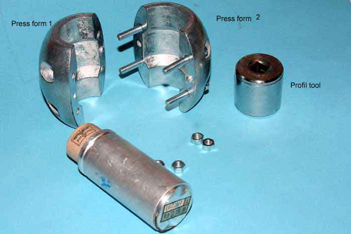
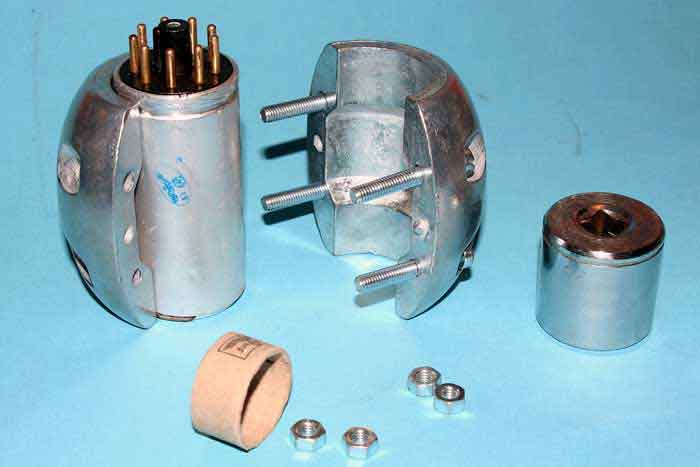
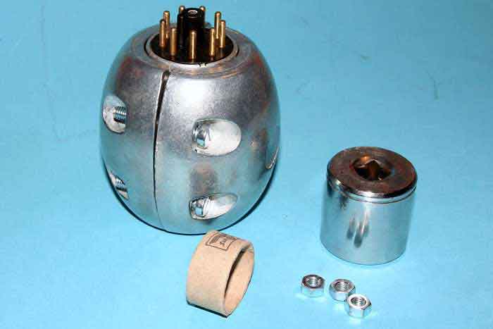
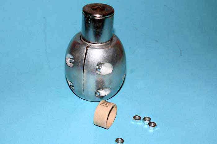
Normally, any Vibrators from Wehrmacht WGL 2.4a new,would not start after staying in the orginal package after 60 years.The problem is that it is not packed in clean air.The start contact have a thin film on it,they other to,but this let no current go through to induct the coil.Therefore it it necessary to open it up,and clean the contact(s),or adjust the spring setting screw.Open up the unit is some tricky without disturbing the alluminium alloy.Place it together is more awefully.This tools make it all handy.First the vibrator is placed into the pressform, and the screw is tighten well.then the all-alloy is bend backward with a knife,and the vibrator is taken out for adjustment.Then back in the can, the Profil tools bend back the allu-alloy.The alluminium edge is profiled back like new.This tools took me a lot of time to figure out.The press-tools weight about 2 kg and steady to work with. I opened the vibrator and adjusted it,working well,like new. A problem with this vibrators are the mechanical noise. The damper (some sort of rubber) seems to have been chrimped after all this years.So,after the adjustment(s) the profil-tools clamp the pin-bracket down ca 1mm when it profiles the alluminium-edge.This is enough to press the rubber to the bottom and the side of the can. It is VERY important, when vibrator is reasembled,that the can edge-profile tighten all around the pin-bracket very hard,so no vibrations could go on. This is not possible without this 2 press-tools.This tools work well (40mm ø) with all the russian types of vibrators. They are copies of the German WWII types.Only the contacs and pins differ. ABOUT VIBRATOR and VOLTAGE.

![]()
![]()
Founded in 1936 in Wien when the Austrian arm of Philips took over
the bankrupt Vindobona company. This turned out to be a smart move on
Philips part as they were the main creditor and supplier of the original company
and would thus have lost out if the company had not survived, further more the
Hornyphon brand had become well known in Germany and Britain in addition
to being by far the biggest supplier of radios etc. in Austria and became
profitable soon after production was restarted. From it's founding
throughout WWII
,producing military radios, and
until 1947 the company was mostly occupied with the manufacture of it's own
products but after that period Philips increasingly began to integrate the sales
and branding of the various companies they owned world-wide and Philips products
began to appear in Austria branded Hornyphon and products from RH were
increasingly sold outside of it's home country branded as Philips, by the 60's
the Hornyphon name had all but disappeared except as a local brand. The
factories continued however and were for a time the main source of certain tape
recorders lines from Philips, their excellent but seldom seen professional tape
recorders were for instance designed and manufactured at the RH factory and
later some video recorder lines were produced there as well. The usage of the
Hornyphon trademark appears to have been dropped in the 1980's and I have not
been able to find out for certain if the factory is still going but I believe it
was one of the factories that disappeared in the "Rationalisation Programme" of
Philips in the early 1990's, when the company sold and shut down a large number
of product lines, technologies and factories in an effort to simplify it's
management and financial structure (remember "downsizing" was
Radiowerk Saba A.G (Schwarzwälder Apparate-Bau-Anstalt)
1933: Schwarzwälder-Apparate-Bau-Anstalt August Schwer Söhne GmbH; Kurzform: SABA Radio Werke.Saba have produced sivil radios since 1933,and the products on market was on this time higher than Telefunken and the quality very high. So when the WWII start,Wehrmacht take over the production and begin making radio-parts to the war industry.1942 Saba starting making complet radio units,like Feld.Fu.b1 /b and c "tornister gerate",but still making parts to other radio factories.Saba A.G make radio-type Tornister Torn Fu.g series for a while to.Meny of this factories was spreed around,mostely in east (DDR) and therefore the russian army after the WWII keep this factories, and making their own equipment, Warsawa packt .
Staru A.G (Telefunken)
It is little writing about Staru A.G. As known,this factory starting making radio equipments for Wehrmacht in 1938.It seems that this factory constructed the first radioequipments, like Feld Fu.h .As I have found,Staru is the constructor of this unit first time,and some later Feld Fu.b and c.Later this was produced on many other radio factories from 1942-43.Staru AG ,a part of Telefunken,making radio remote controls earlier testing rockets with wire controls.
Radiowerk Lorenz A.G ( Lorenz A G., C., Telephone -Telegraphenwerke, Berlin - Tempelhof)
About Lorenz,it was one of the bigger factories before the WWII in Germany. As other radio /signal supliers,they was soon incorporated in war productions.As I have found out,earlier,1939-42 they was involved in making Tornister Feld.Fu. series for Wehrmacht.Later they productions of this unit was taken over by Saba and Horny Radiowerke.Lorenz consentrated the productions of greater transmitters 50-1000w for stationery operations,together with Telefunken/Philips.This time they make telephone/line,and connecting equipment to radios.
| Feldfu.a1 | 120-156 MHZ Infantry, Einsatz heer |
| Feldfu b | 90-110MHZ Infantry |
| b1 | Pioniere 90-110Mhz |
| b2 | Panzer grenadier only 2 tubes,no AF tube Rv2,4P700 |
| Feldfu c | 130 - 160 MHZ Infantry, Einsatz heer |
| Feldfu .f | 28. 0 - 33.0 MHz Panzergrenadier |
| Feldfu .h | 23.1 - 28.0 MHz Sturmgeschutz-einheiten |
| Kl.Fuspr.d | 32.0 -38.0 MHz Artillery Beobacher (Arty F.O.) |
Feld.Fu.a1 0.150w 120-156MHz
RV2P800 SD1A RL2P3 Ant base-color dark brown
steel-blade ca 66cm
Feld.Fu.b 0.150w
90-110MHz Ant
base-color dark red steel-blade
72,5cm
Feld.Fu.b1 0.150w 90-110MHz
Ant base-color dark red
steel-blade 72,5cm
Feld.Fu.b2 0.120w 90-110MHz 2
tubes
Ant base-color dark red
steel-blade 72,5cm
Feld.Fu.c 0.150w
130-160MHz
Ant base-color dark green steel-blade
66 cm
Feld.Fu.f 0.150w
28.0-33.0MHz
Ant base-color
white
steel-blade 1,20m
Feld.Fu.h 0.150w
23.1-28.0MHz
Ant base-color dark blue
steel-blade 1.50 m
Stassfurter A.G (Stassfurter Licht-und kraftwerke AG.Stassfurt)
|
||||||
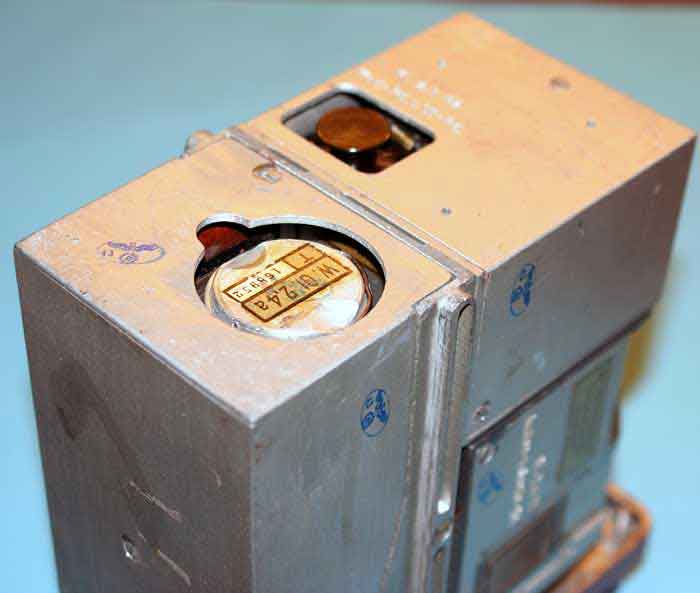
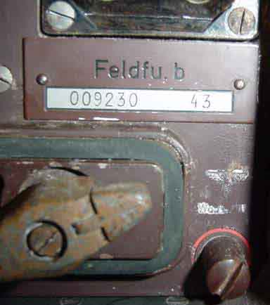
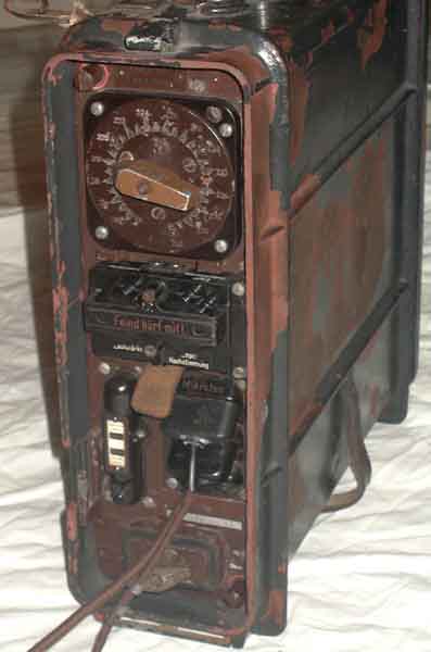
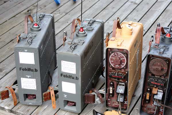
 Feldfu.b red mark 104Mhz. Feldfu. c 156Mhz
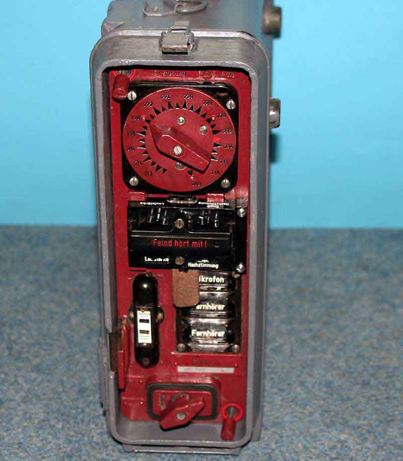
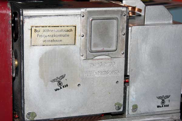
After 60 years of inoperativity,the frequency have drifting between the transmitter and receiver. This is normal,and when listning to a receiver freq 104.0Mhz (the red arrow on channel selector),the transmitter working off frequency.This could be corrected with receiver tuning,but ,for the most,it is impossible. Some unit going down in frequency,as, rx 104.00 then tx transmit on 103,100 to 103,400Mhz. This make it impossible to have communications between to units or more,the rx tuner adjustment could not catch the frequency. This adjusment controll working about +250 and -250Kcs of the rx center.
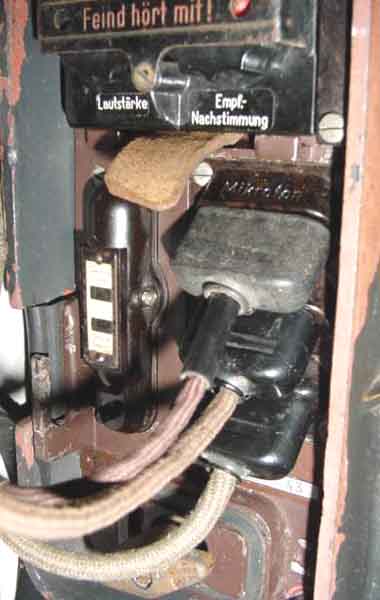
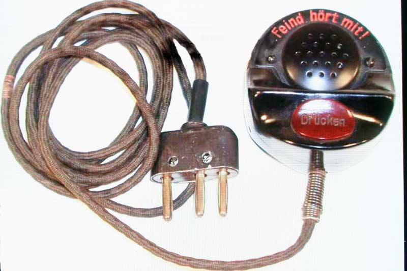
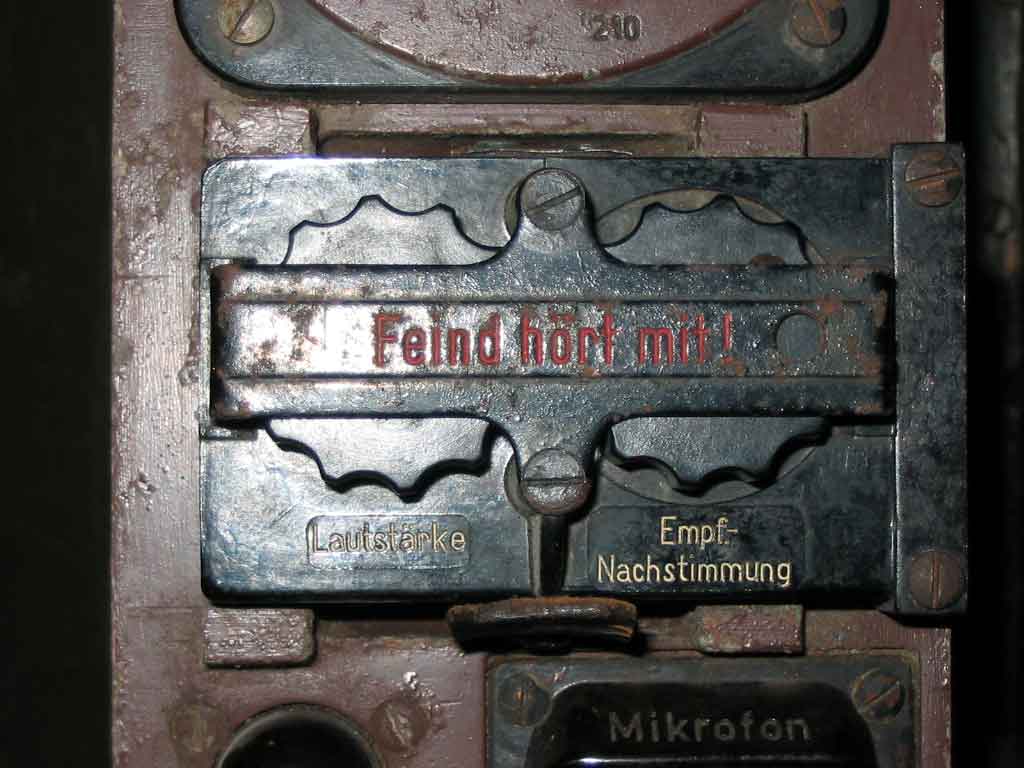
I prefer to readjust the radio from the beginning. First of all,you may have a signal generator. Adjust it to 104 Mhz and Feld fu.b channelselector to red mark.As the feld fu.b do not have 50 ohm coax connector,make a wire ca 30cm. Put it in on center of output connector and to antenna on the radio.Set the generator to about 60uV.Now,on the right upper corner it is a adjustment hole. With a isolated tuning pin,adjust C8 to minimum noise in the earphone. (freq still 104.00Mhz.) Connect a frq-counter near the antenne wire.Now,you may loosen the 3 screws holding the front cover with the channelmarkings. Then move the "Stop" screw.On the left side of the calibrating hole, you see a new one,some smaller,with a condensator inside C9. Push the transmitter and carefully adjust this condensator to correct freq,so near 104,00Mhz as possible.Reasemble the channel cover. Now the TX and RX frequency going on same "Channel" with the red mark on the controll box, the hole to right of "Feind hort mit." If another transmitter stay out of "channel" you could now, tune in with the knob to hear clear communications.
The superregenerative receiver uses a quenching oscillator to permit high positive regeneration of the radio amplifying stage, while quenching or keying the built up regenerative oscillation at an ultrasonic rate. This further improved the gain of the receiver while simplifying adjustment. The regenerative radio made the most out of very few parts. When the parts became easier to obtain, the superheterodyne receiver replaced it for all serious work. The superheterodyne receiver is the most common receiver in use today.
The sensitivity for Feld Fu.b is not to write at home. If the radio working as the producer wanted,the radio receiver let you have about 2 uV /52 ohm,when the noise going down 5db. With other word,you could hear the voice speaking weak into the noise. This poor receiver sensitivity doing it possible to have communications only about 1-1.5km .This is given into the service and user manual.Solid covering in low hilly surface. Free sight the unit talk up to 5-6km.
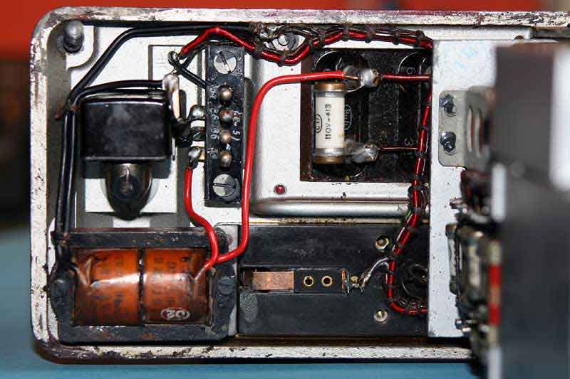
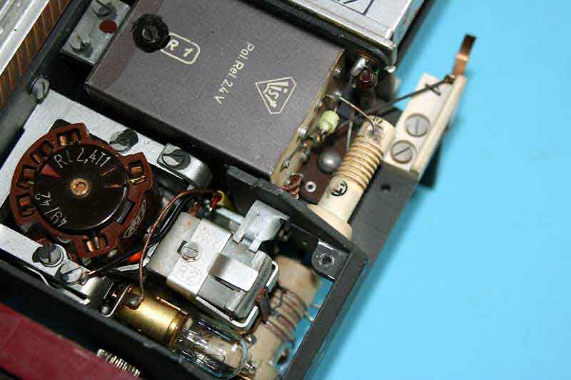
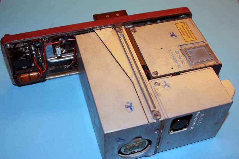
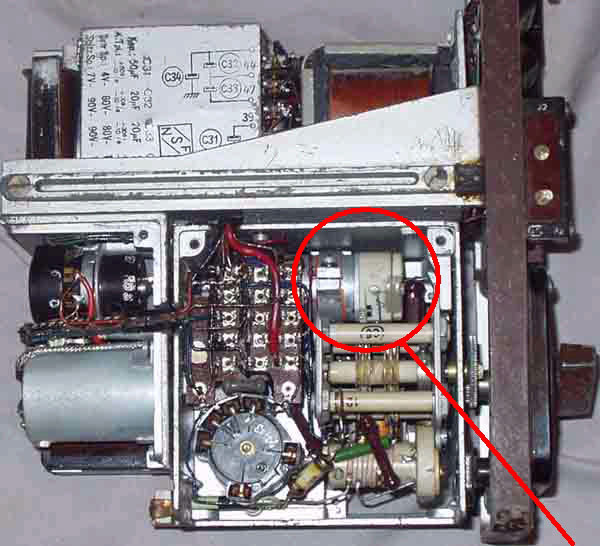
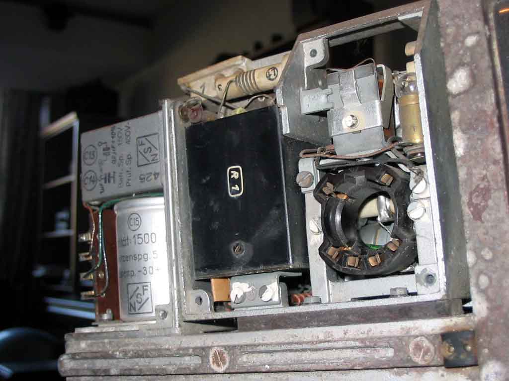
Known problems about Feld Fu.b/c/b1/b2 after 60 years,is the vibrator and the relay unit. RL1. The contacts into this relay become dirty as the can is not air sealed. When pushing the mic somtimes it would not switch between the voltage from regenerative voltage to voltage from mic-modulator. It is no modulation and low power from transmitter.Anytime this relay may be cleaned and adjusted. To remove the relay from the radiounit,all the cables must bee soldered away from the connector-plate mounted on the other side of the unit. This way is not to prefer,it is possible to solder the wire and melting the isolation. My way to do this ,a little tricky,but a nice methode.Loosen the little screw on the can,then loosen the 2 connecting screws to chassis. Solder away all the leaders on the top (antenna). Then move the relay upwards,obout 45 degrees.On the can it is again a little screw on other side. Going in from the connector-plate a little bit to left with a small screwdriver to enter the screw. Turn it out. Now it is possible to move away the can.(somtimes it is glue around the can bottom). Clean the contacts with "Video spray" and adjust the conntacts to work all the same way. Reasemble the same way. Have a small "beewax" on the screwdriver tip,to hold the little screw for backside of the relay can,and enter the screw. The relay contacts seems to be one of the points where it it doing sabotage on the factory.The most of the contacts it not adjustet "online",one or two is bend a little to mutch away from opsite contact. This will after short operating in the field, make the set useless.It is inside the relay can,and a excelent place to make sabotage,it could not bee seen.
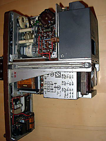
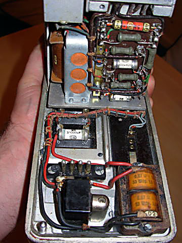
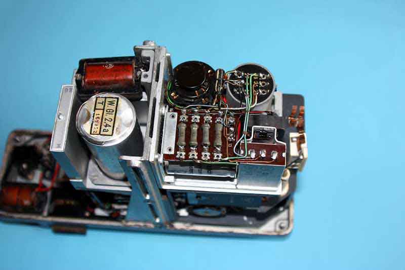
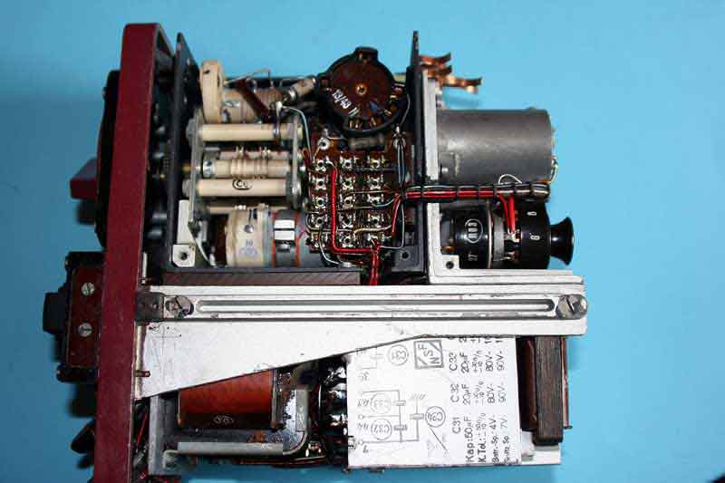
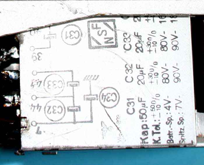
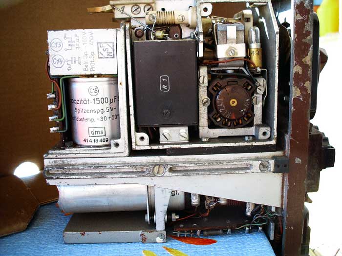
Power supply, vibrator unit normally giving on Rx ca 130vdc with accu voltage 2.4vdc.On Tx mode the voltage falling down to 118v.After 60 years the capacitors is burn out (the lyte is vapored) on electrolyte cond,and paper condensators.In the AF part of the radio,it is a big can 1500uF 5v standing between + and - 2.4vdc. If this is not working , you hear a dark hum in headphone.In this power you have a combi-can with 4 electrolytes C31-32-33-34. This must be changed.You need to demount some parts in AF unit to loosen the screws. Bend back the tags on the can,then change out, to new modern condensers. This old condensers let the voltage drop to 70-80vdc or shortcut the highvoltage. On the bottom of the vibrator unit it is likely a can with 5 capacitors (0.47uF). This is spark condensers for the vibrator contacts. This is more seldom needing to changes,but be care of them.(Old capacitors
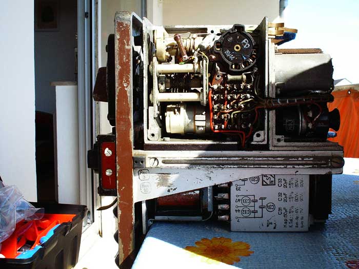
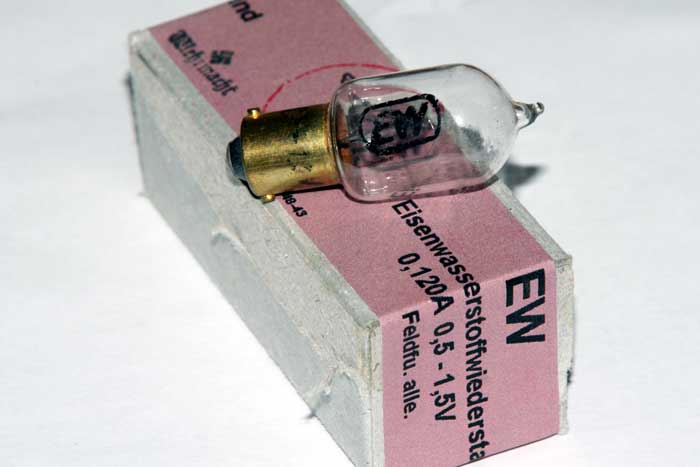
Regulator,like a normal bulb,besides the coil-relay,inside of the transmitter tube compartment,regulate the voltage to the "moving coil" controlling the stability when tuning on the controll box."Empfanger nachstimmung".Sometimes this regulator is gone.The "Eisenwasserstoff-Wiederstand" bulb have spec,J=0.12A +- 5%,U=0.5 to 1.5v.If you insert a ordinary bulb,you may burn off the "movingcoil" for the receiver adjustment.
Voltages,from the vibrator depends only how the vibrator works.On the primare side of the trafo,it oscillate around 80Hz,and not critical between 70-90Hz. The secundary side is a voltage doubler.If opening up the vibrator,it is not enough,with adjustment to let it start,but adjustment of the conntacts all around. This is only possible to have done with the Feld Fu.b opened ,connected external battery near 2.4vdc to it,and turn away the chield-box covering the vibrator unit.Connect a voltage meter to earth and + on condenser C34. When the vibrator can is off,be care when you insert the vibrator socket into Feld Fu socket.It could be difficult to move out again.Therefore connect a thin wire under the socket to pull it out again.No, do you adjust the vibrator to giving around 128-130vdc in Receive mod.Transmit mode pull down the voltage to ca 118-1123 vdc.Normally you need to push and pull out the vibrator many times for adjustments.Finished Here to,the wire from main power contact + 2.4vdc to vibrator input (filter coils) ca 15cm long,is very thin,let the voltage going down with 0.6v with transmit.I think this to is one of the sabotages doing of the workers on the factory.This little sabotage let the radio operate shorter in the field,as the voltage indicator on front tells the operator to change the battery.After change this wire with a heavier one,the radio functions mutch better.
The most of the vibrators opened and fixed only to run again,giving ca 112-114vdc in Rx and 87-93v Tx ,this let the Feld Fu work very poor.Some other thing to be aware of,is the battery connections inside,from battery cable to the connections box.Here,the screws have 100% corrosions.This connetions + and - have a brass shunt,with 2 screws each.The upper, on both sides have no threads in the bakelite? I suspect the workers on the vibrator factory,to sabotage the productions.To many vibrators have readjusted contacts,let it giving low voltage to the radio.(New 112-114v and readjustet carefully,128-130v) The center pendel adjustm are importent.

 Telefunken AG. Hersteller Funkgeraten
Documents,drawings etc. Dokumente, Zeichnungen usw..
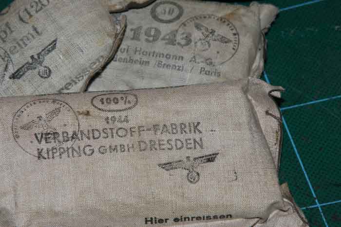
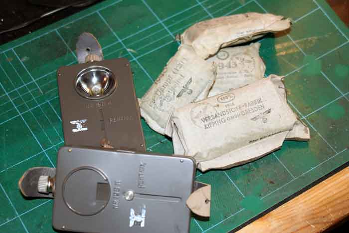
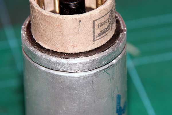
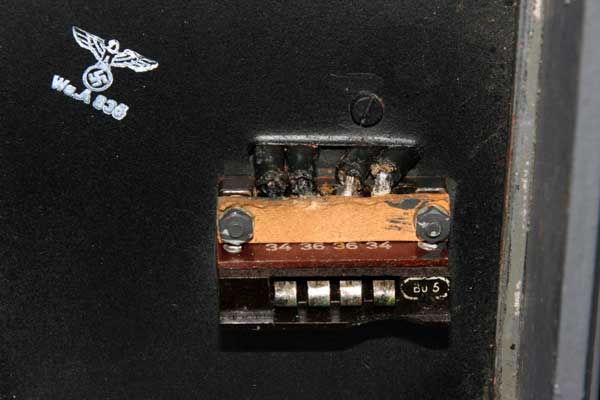
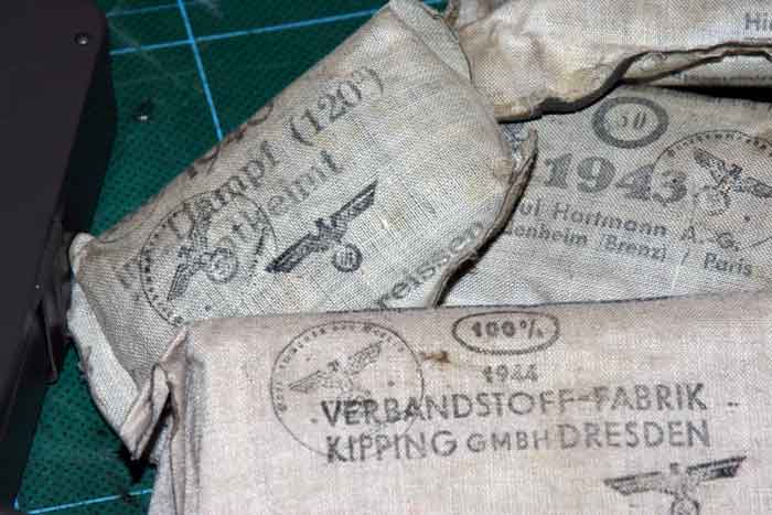 "Wehrmacht Verband Packung",orginal sealed.
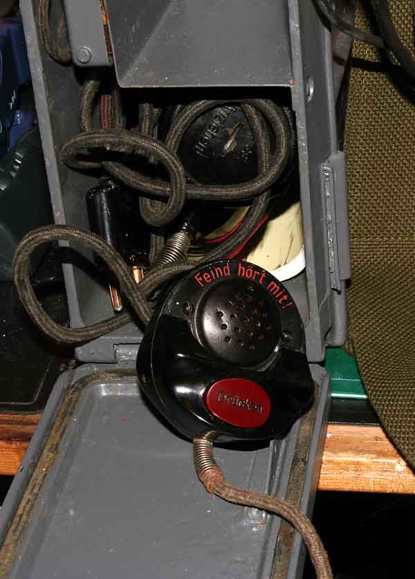
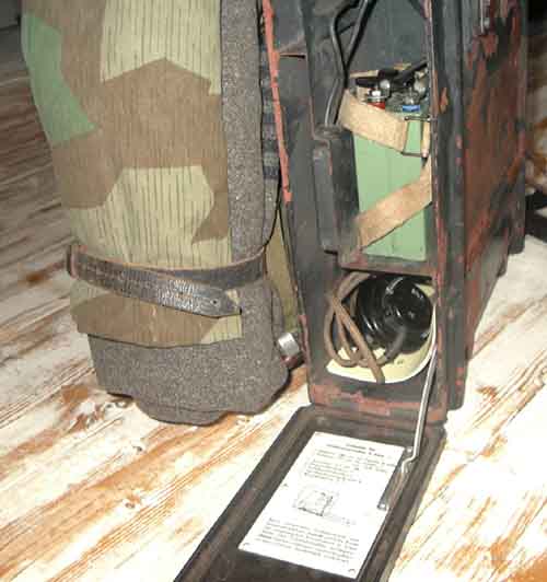
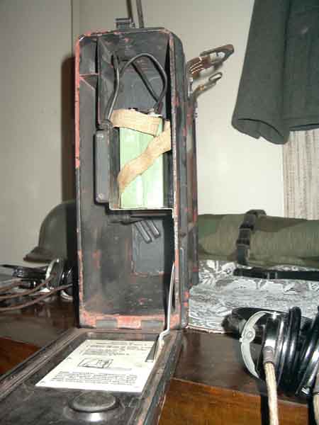
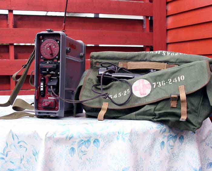
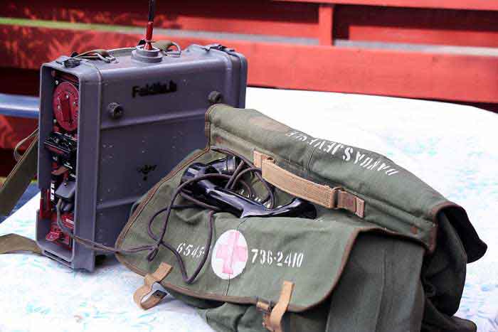
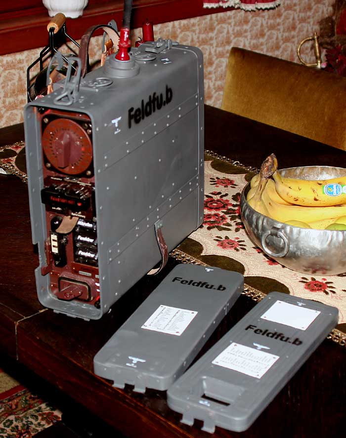
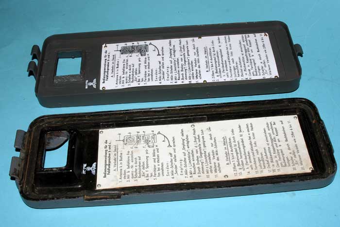
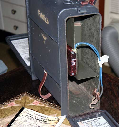
This soldier "verband packung" 2 pieces,stay normal into the Feld Fu box,inside, under the battery compartment,where the mic, hear-phone and antenna,was hidden.It seems to be a part of the radio unit,together with 1 light unit. (Not verified)
Dieser Soldat "verbandpackung" 2 Stücke, bleiben in den Kasten Feld Fu, Innere, unter dem Batterieraum normal, in dem das mic, das Hörentelefon und Antenne sind.It scheint, ein Teil der Radiomaßeinheit, zusammen mit 1 heller Maßeinheit zu sein waren.
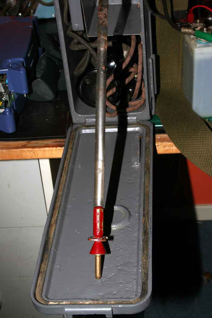
Feld Fu.b 1941,the first antenna for this radiounits.
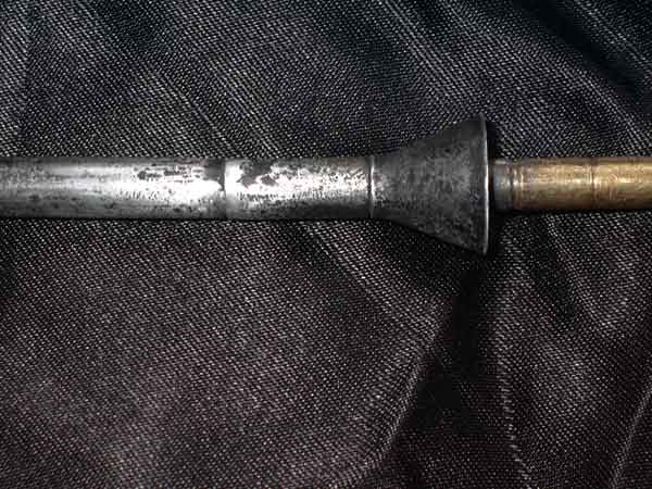
![]() The Rod antenna in two parts.
The Rod antenna in two parts.
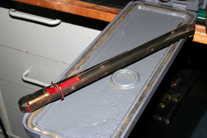
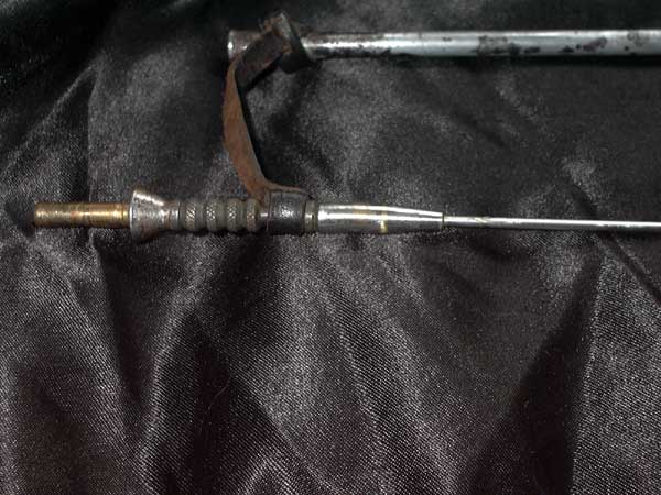
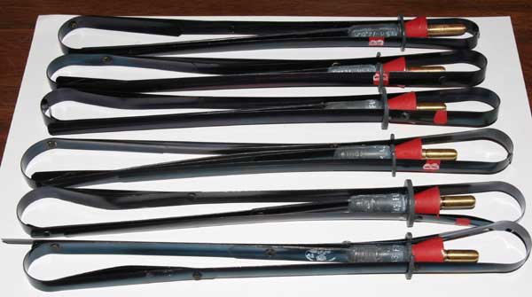
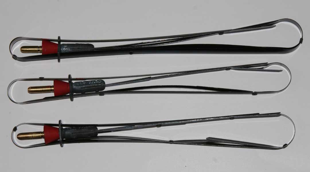
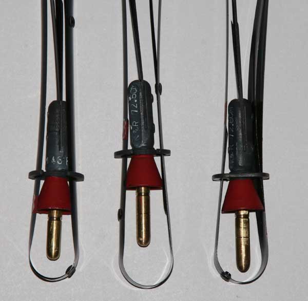
Feld Fu.b 1/4 wave antenna model 1943 flexible-blade antenna.
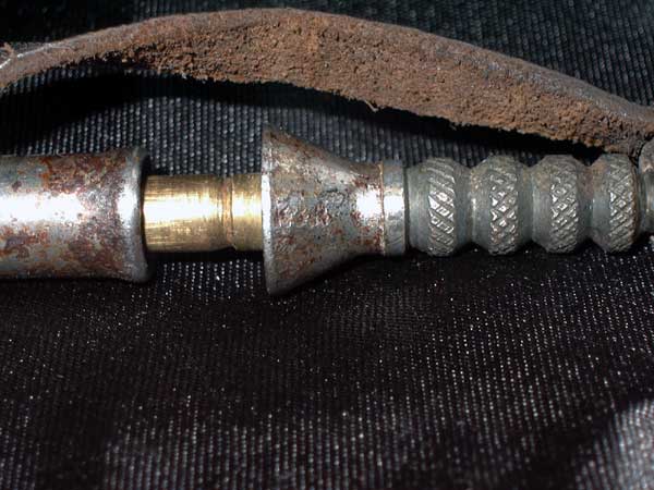
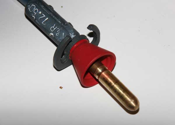
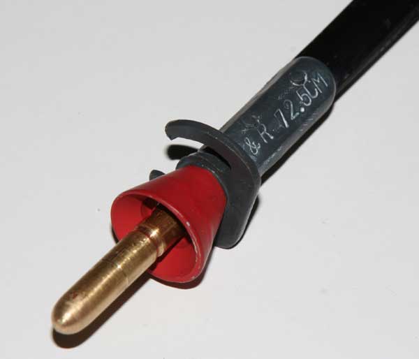
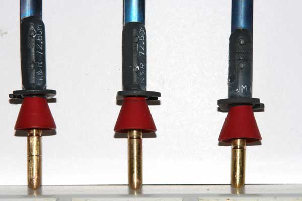
.The antenna to b and b1 freq is 90-110Mhz 1/4 wave, and 130-160Mhz to c models.The antenna for b models is red and c model green on the connector head.The lenght of the antenna for feldfu.b is ca 72,5cm.and for c model ca 66cm.The distances you get from the radio is depending on correct antenna lenght.(It is critical), as the power is very low.Antennas in 1940 to 1942 is very long,maybe a 5/8 wave antenna.Later in 1943 the 1/4wave antenna was mounted.It seems the radio operate mutch better with this type of antennas.The connector is made of pur solid brass.The colour shade could have some differences on the photos.It appear some colours on the upper part of the connector,some grey,blue and red.
![]()
![]()
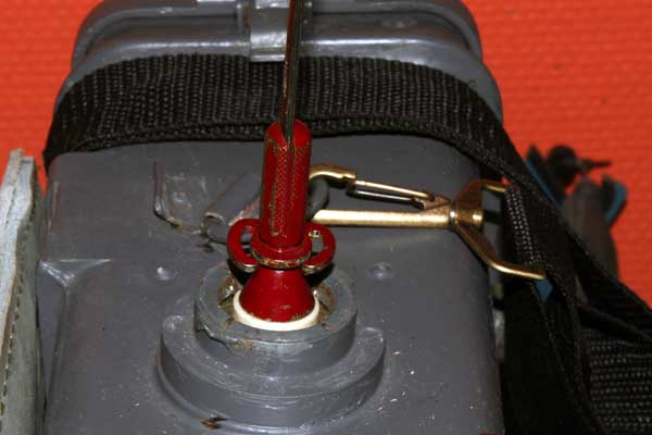
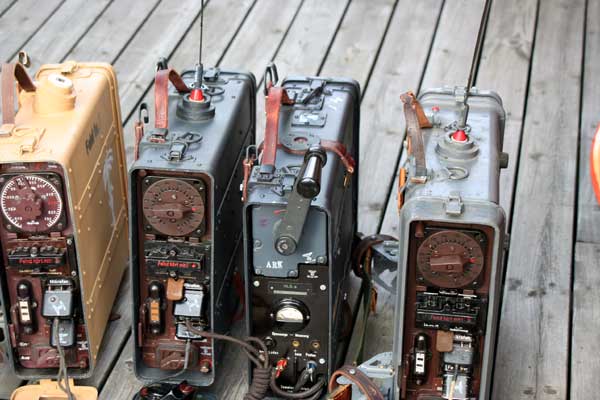
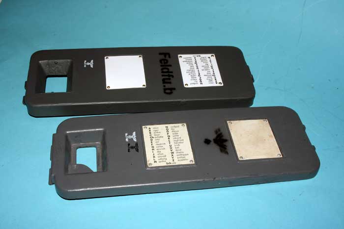
Feldfu base apear with colors:Green for "c",red for "b" and White for "f"
The antenna for feldfu.c is similar but cut to 66cm long, and connector is dark green as orginal.
Color for Feldfu front paint.
The original paint color are a brown/red mixed paint.Mutch like "Chocolate" RAL 8017 matt.It is original like the German Feldfu paint.
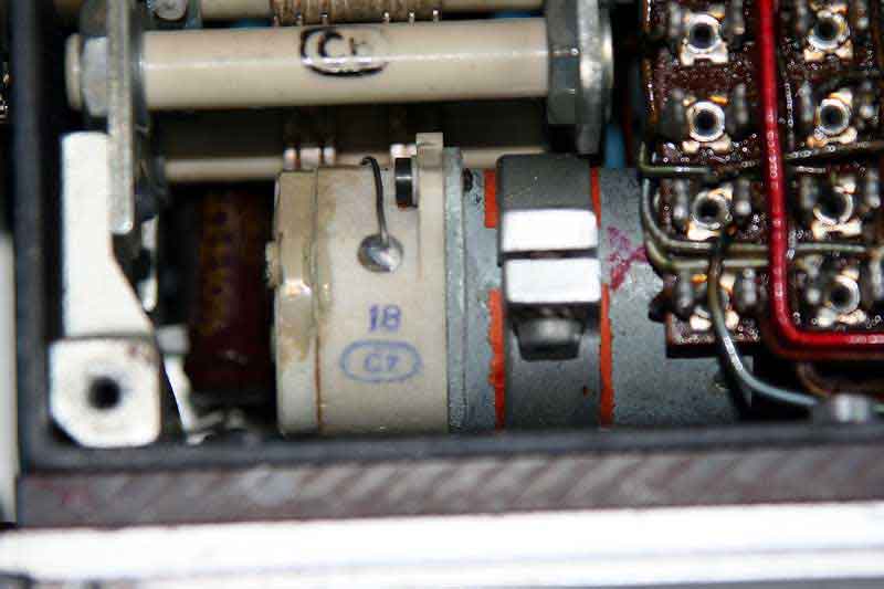
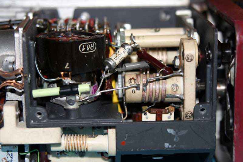
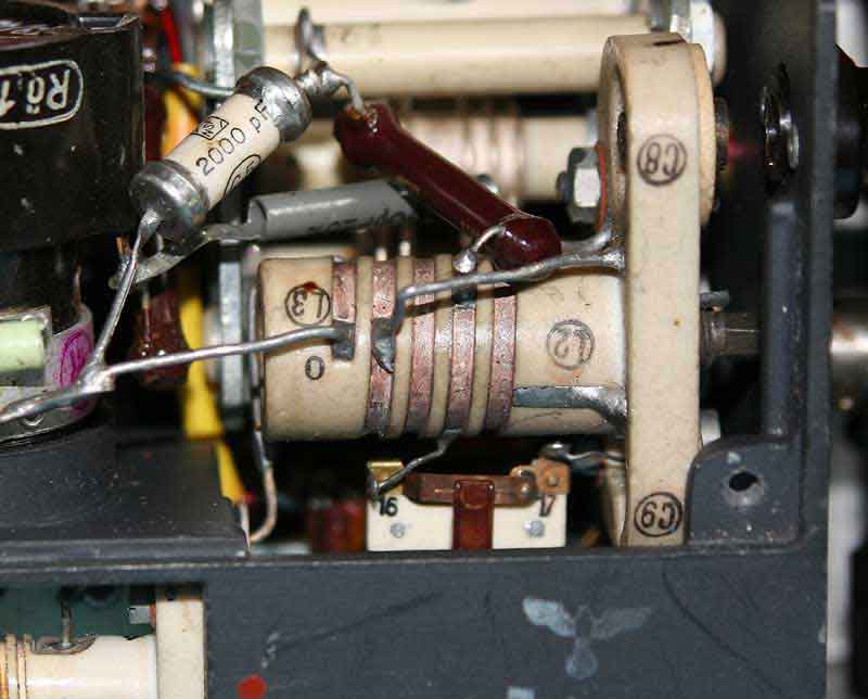
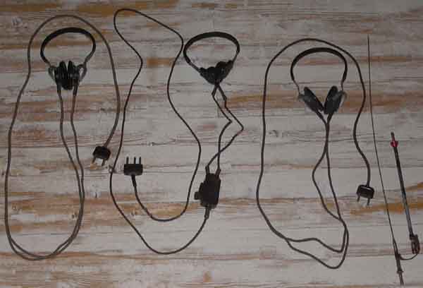
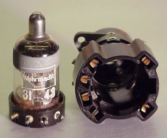
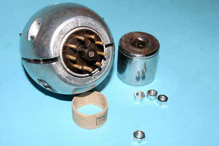
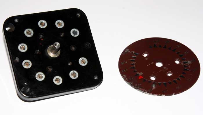
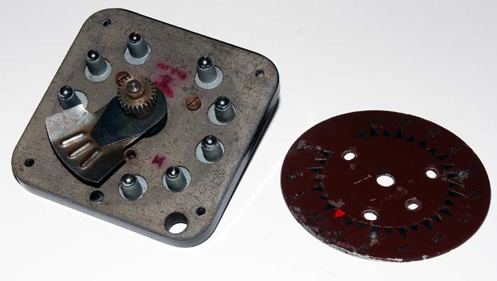
The Moving coil (Freq adjustment)
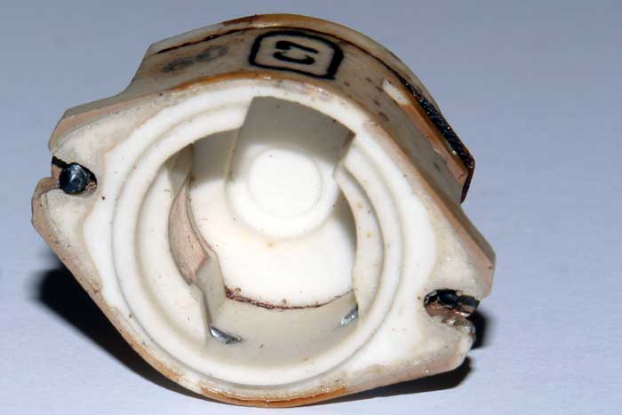
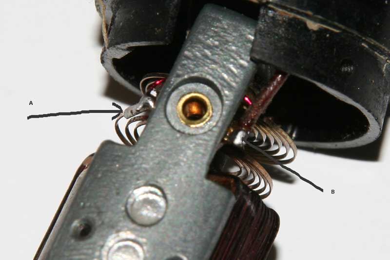
This moving coil was broken,no receiver adjustments was possible.As picture 3 from left show,A and B was broken.This is a through connector,between the motor house connector,and the rotor. Through point A and B ,a brass joining,it was broken right under the pertinax isolator.It seems this was done on the factory.After a time it will not working. Productions year 1944,when great sabotages was done by the workers.(prisoners).Well,now,it work again.
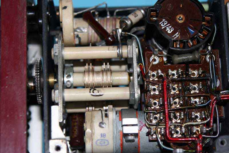
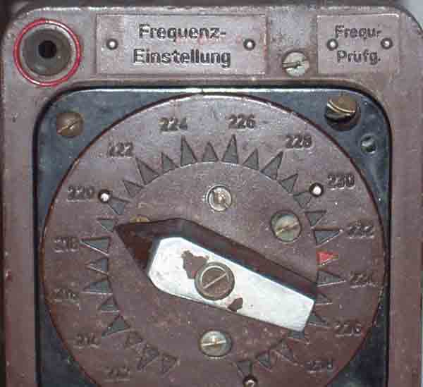
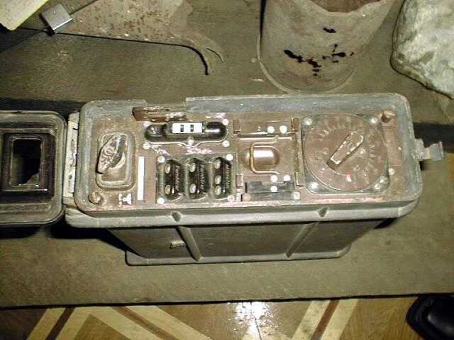
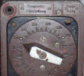
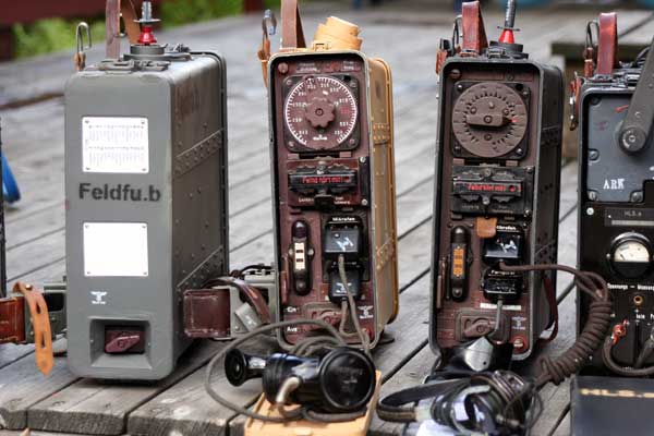
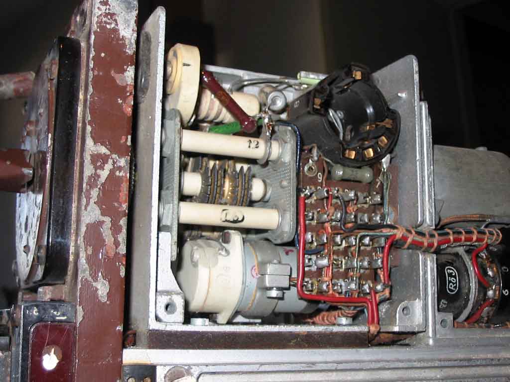
The frequence adjustment switch.Feld Fu.b and c
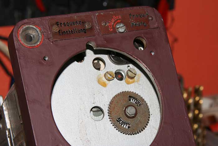
 This is a complex adjusments.Picture 1 left,show thw
adjustments.First set the switch to "Red" mark.Here the freq should be adjustet
for 104 Mhz on the receiver.(Hole on right through the switch front.). Then
transmit and adjust the transmitter condenser,through hole upper left inside the
front,to 104 Mhz. Thats it.If the switch not corresponding with the front
marks,picture 2,loosen the senter screw,locking the excenter bear roller
house.All 10 rollers is factory made as a unit,and could make a excentric
moving.This will get you a lot of work,DO NOT TOUCH!
It is possible to do the test with a x-tall
oscillator on 26 Mhz.It giving 4 harmonics on 104Mhz on receive.
This is a complex adjusments.Picture 1 left,show thw
adjustments.First set the switch to "Red" mark.Here the freq should be adjustet
for 104 Mhz on the receiver.(Hole on right through the switch front.). Then
transmit and adjust the transmitter condenser,through hole upper left inside the
front,to 104 Mhz. Thats it.If the switch not corresponding with the front
marks,picture 2,loosen the senter screw,locking the excenter bear roller
house.All 10 rollers is factory made as a unit,and could make a excentric
moving.This will get you a lot of work,DO NOT TOUCH!
It is possible to do the test with a x-tall
oscillator on 26 Mhz.It giving 4 harmonics on 104Mhz on receive.
New this year 2 Feld Fu´s 1 Feld Fu.b and 1 Feld Fu.b1.
 I get 2 feldfu´s units this year.I get them
from persons in Leipzig.They was in bad conditions. All the paint was more, and
less loosen from front,and they do not work at all.The "b" set was the
moving coil broken (adjusting
the RX freq) and vibrator do not work. The condensators was leaky ,and small
corrosion around inside the unit.The "b1" same as "b" unit,but with small
chassis changes.B1 unit was produced in 1944,the most sabotages was going on
around the radio factories and other places making war equipments.After
deassembling the moving coil,I could see,this
break down was made,for later giving a
faulty operations.On the 1944 unit,also the transformers have break,as
modulations transformer,the mod side ,secundary,was off inside.The same with
transformer for mod tube inputside. To get this transformers to work
again,giving me a lot of work. All at all,I demounted the units.Finishing the
renovations,the unit functions as from factory.The only thing,I have no box to
them,so I am going to the project to
produce boxes.
I get 2 feldfu´s units this year.I get them
from persons in Leipzig.They was in bad conditions. All the paint was more, and
less loosen from front,and they do not work at all.The "b" set was the
moving coil broken (adjusting
the RX freq) and vibrator do not work. The condensators was leaky ,and small
corrosion around inside the unit.The "b1" same as "b" unit,but with small
chassis changes.B1 unit was produced in 1944,the most sabotages was going on
around the radio factories and other places making war equipments.After
deassembling the moving coil,I could see,this
break down was made,for later giving a
faulty operations.On the 1944 unit,also the transformers have break,as
modulations transformer,the mod side ,secundary,was off inside.The same with
transformer for mod tube inputside. To get this transformers to work
again,giving me a lot of work. All at all,I demounted the units.Finishing the
renovations,the unit functions as from factory.The only thing,I have no box to
them,so I am going to the project to
produce boxes.
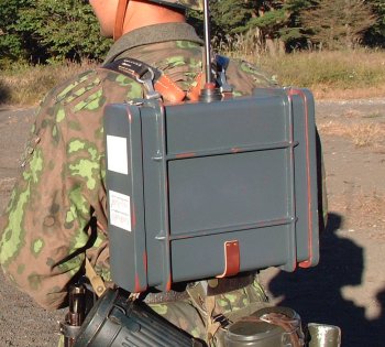
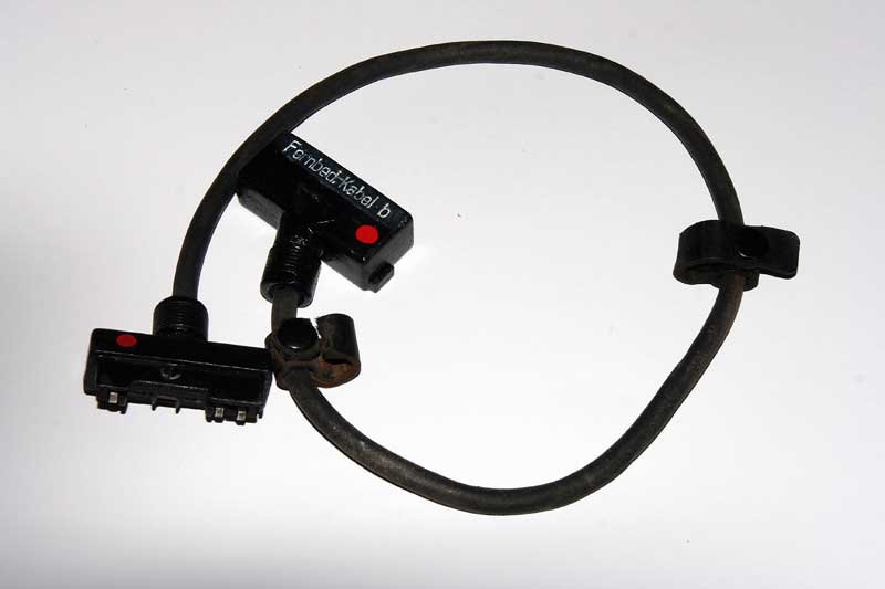
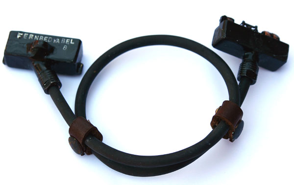
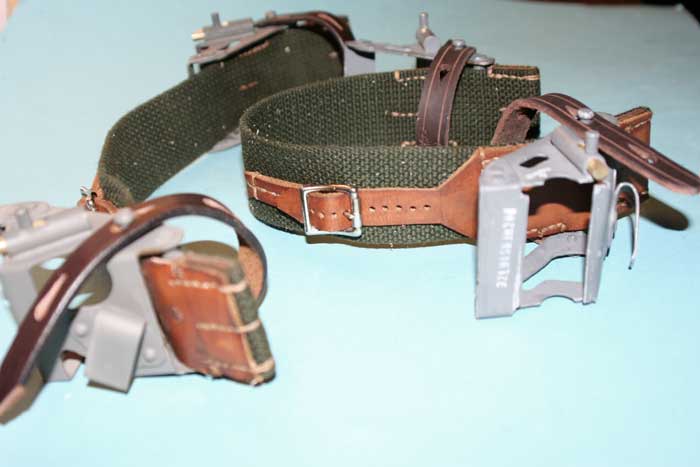
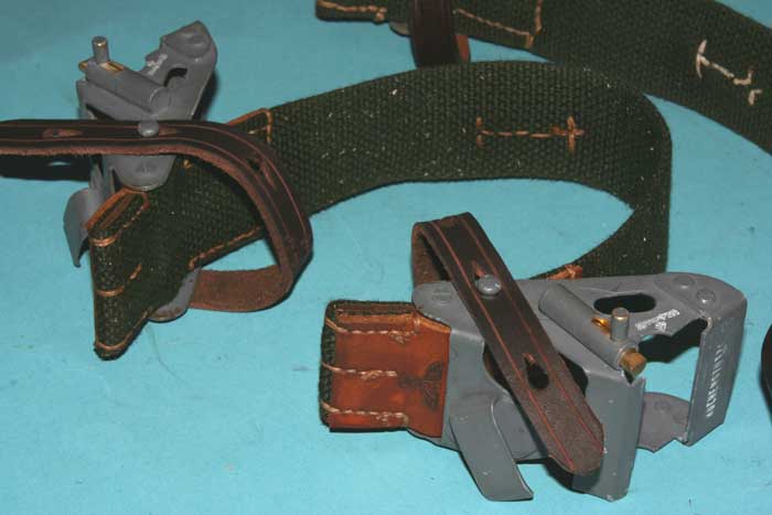
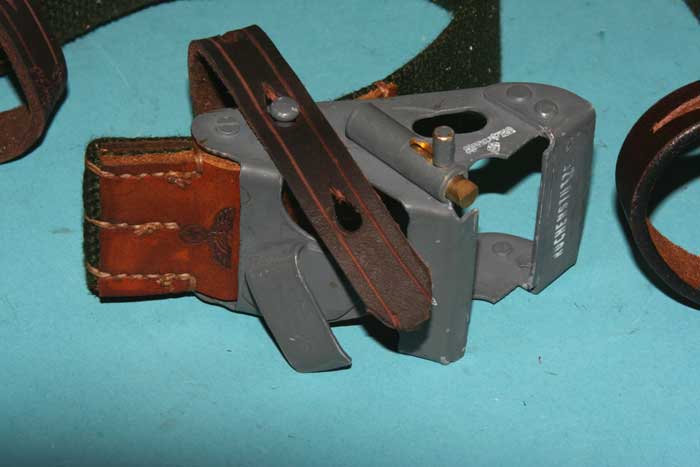
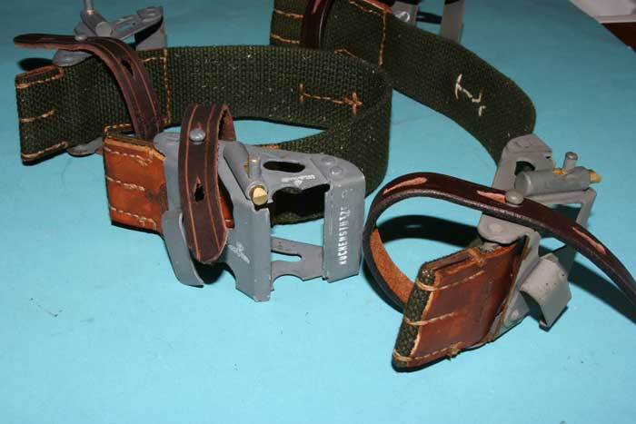
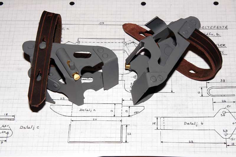
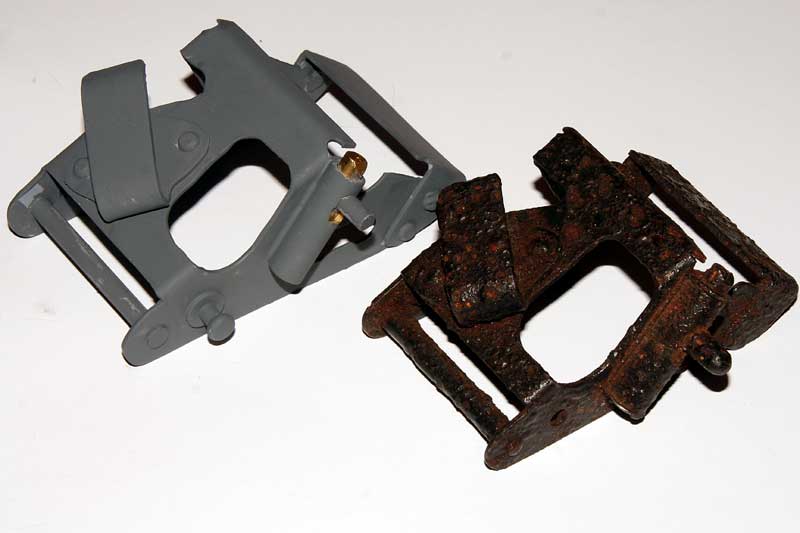
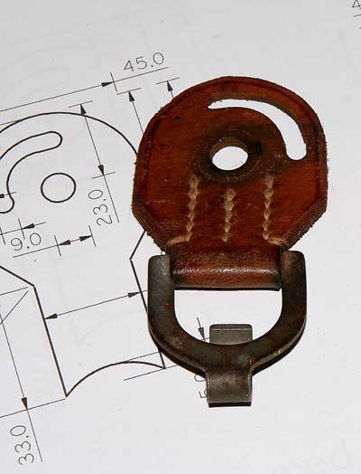
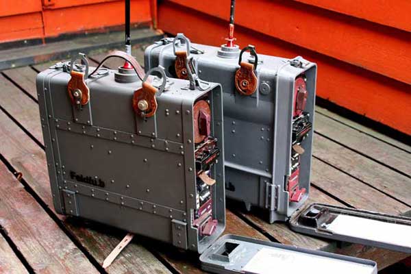
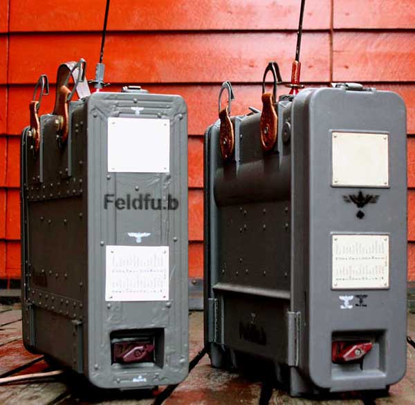
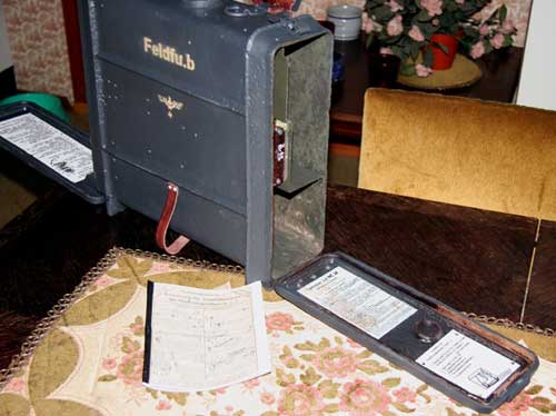
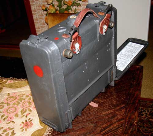
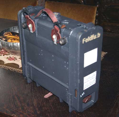
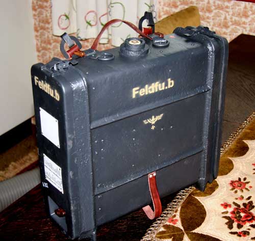
Rest-belt and box connectors left and right down and upper. Feld Fu.
Feld Fu Replica box together with the original. (more pictures)
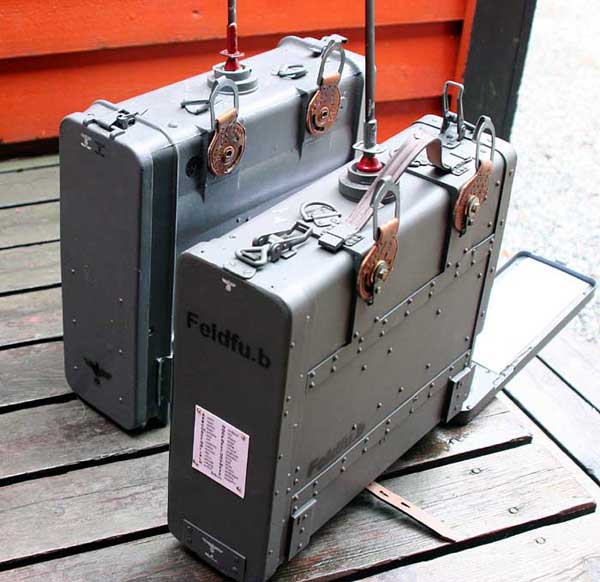
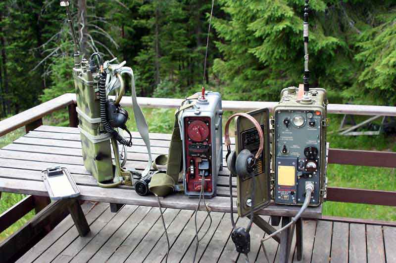
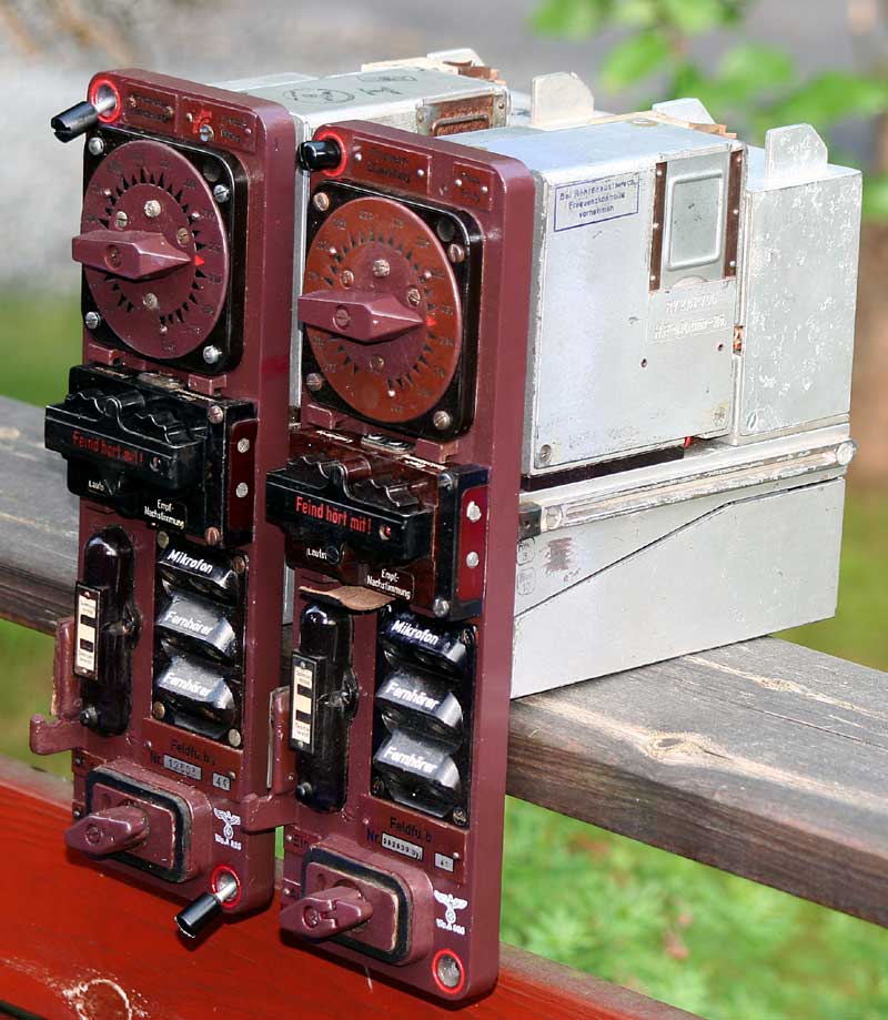
The collection of The Feldfu series field radios.
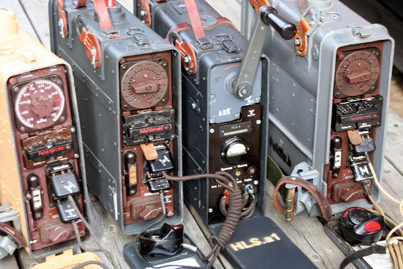
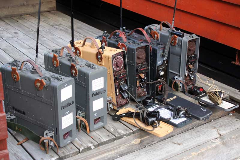
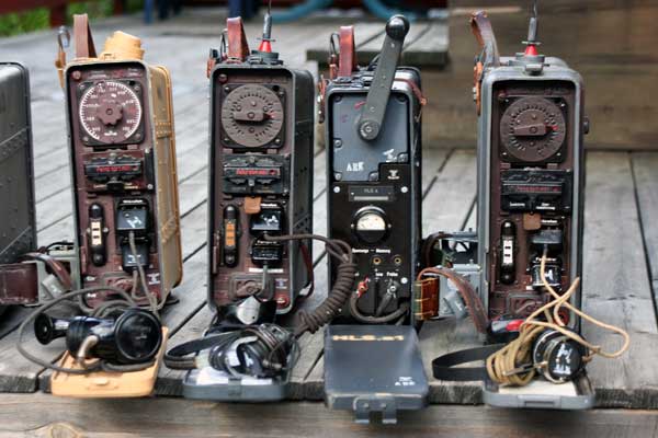
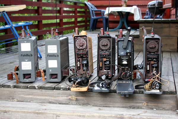
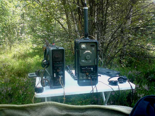
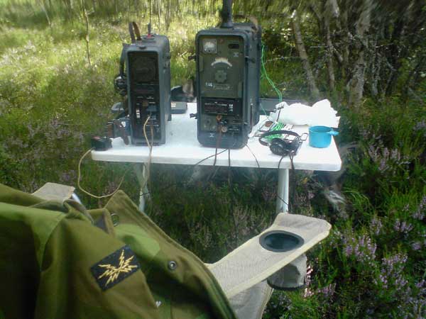
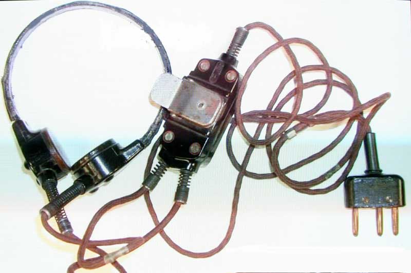
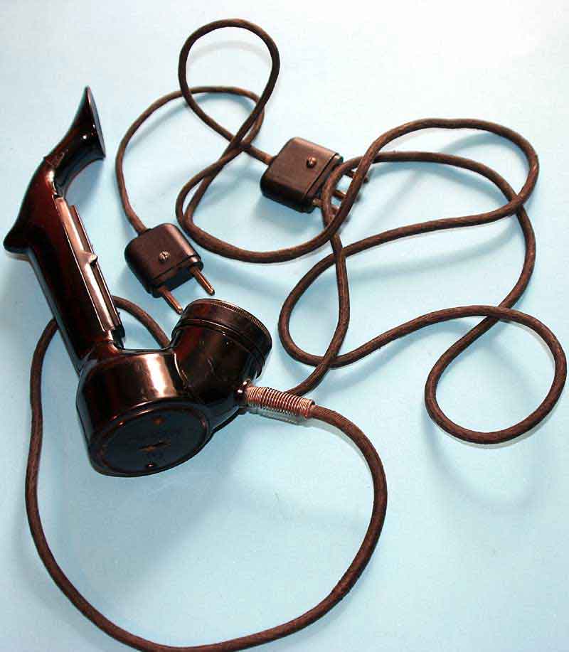
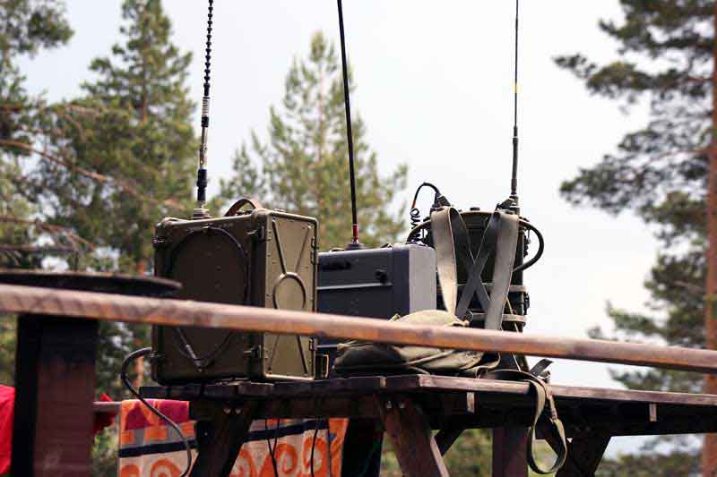
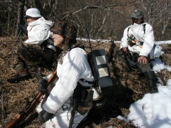
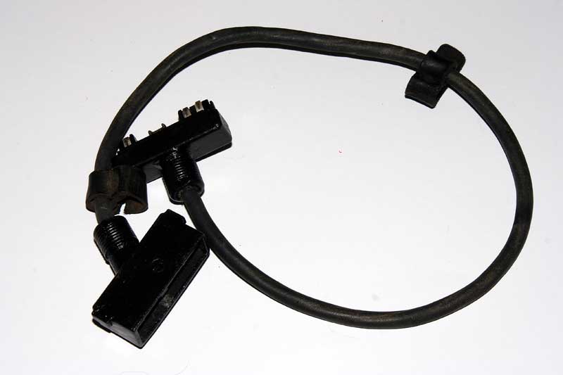
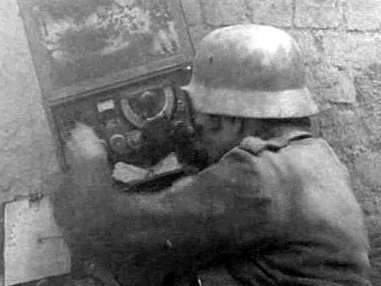
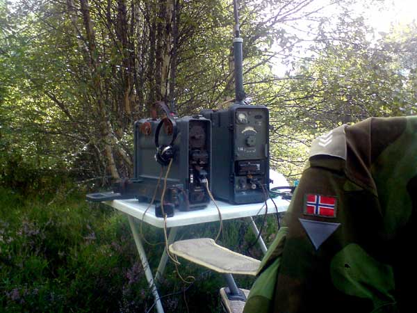 All radioes working with completed mic,hearphone,ant and controll cable to
controllbox (60cm long). Testing the units in the field.The Feldfu b. operating
over 1.8km to another feldfu b. Very nice. See :Tornfu.g
All radioes working with completed mic,hearphone,ant and controll cable to
controllbox (60cm long). Testing the units in the field.The Feldfu b. operating
over 1.8km to another feldfu b. Very nice. See :Tornfu.g
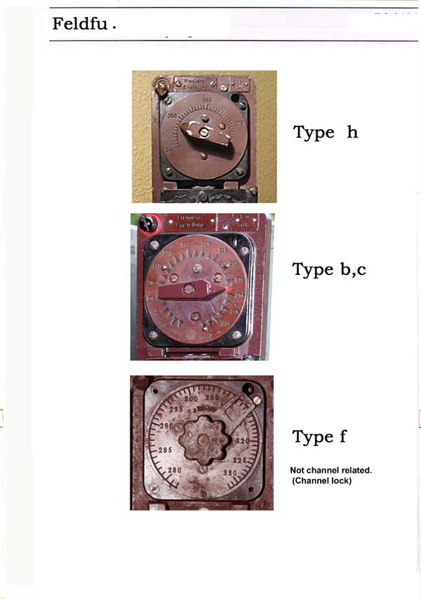
Frontcover and Channel fronts Feldfu b, c, f and h. Feldfu f continius adjustments.
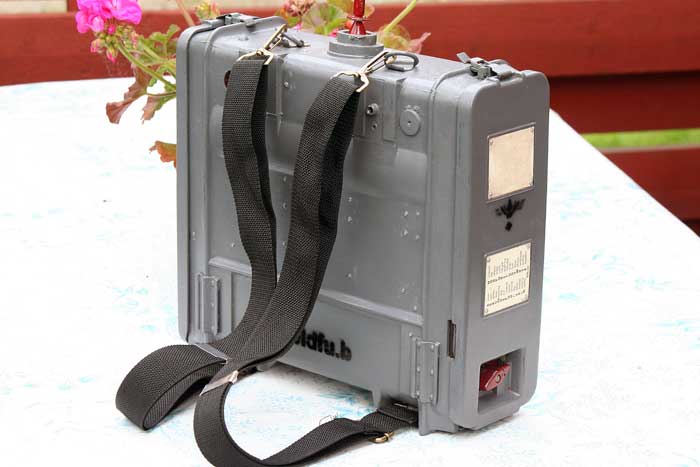
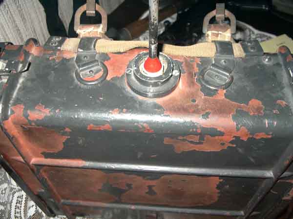
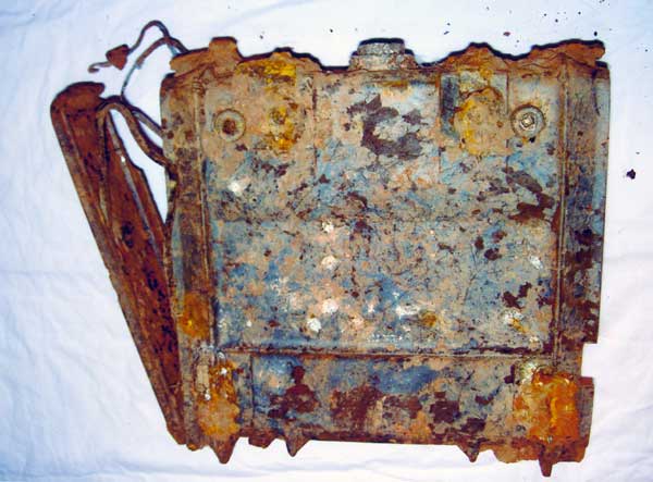
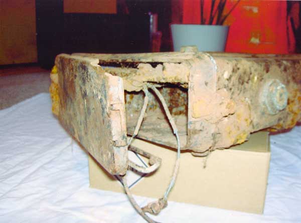
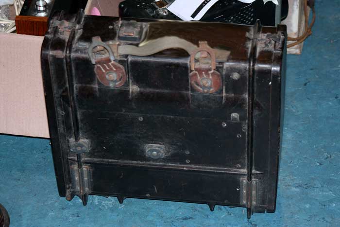
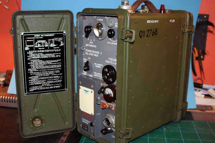
Feldfu box 70 years in the mud and soil.
The Feldfu box was found by Eberhard Knips. He ground restorated the box, moving away all the corroded metall details inside/outside.Build up the box again with a "liquid two component Bakelite" A very,very nice job was doing by him. Later I make all the inside components and other parts.Finished with WH grey paint.The Feldfu radio unit was "ripped" from the most wires. The channel switch was ripped for all Freq lock parts as steel balls and springs.This lock mechanism was rebuilt with pertinax "milled" in one parts.
 Restoring to
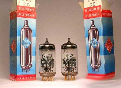
Tubes and regulators to Feld Fu and Torn Fu.g
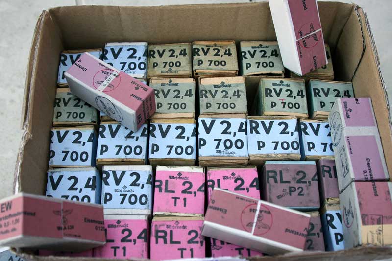
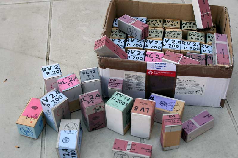
![]() RV2,4P700/RL2,4P2/RL2,4T1 and "Eisenwasserwiederstand"
RV2,4P700/RL2,4P2/RL2,4T1 and "Eisenwasserwiederstand"
This site was last updated 09/03/22 Home
